
Page 109 - Steam Turbines Design, Applications, and Rerating
P. 109
90 Chapter Four
there the buckets are driven around in the groove as required to fill the
wheel by stacking buckets in both directions from a point 180° opposite
the access opening. The wheel is closed in the same manner as de-
scribed previously by fitting and pinning a special locking bucket or
locking piece to fill the bucket access opening. The choice of a locking
bucket or locking piece (essentially a locking bucket root without any
attached airfoil) is dictated by stress considerations. If the weight of an
airfoil would tend to impose prohibitively high stresses on the locking
pin (or pins), the substitution of a locking piece is indicated. The use of
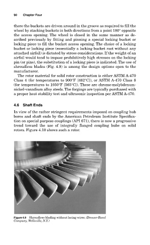
shroudless blades (Fig. 4.9) is among the design options open to the
manufacturer.
The rotor material for solid rotor construction is either ASTM A-470
Class 4 (for temperatures to 900°F [482°C]), or ASTM A-470 Class 8
(for temperatures to 1050°F [565°C]). These are chrome-molybdenum-
nickel-vanadium alloy steels. The forgings are typically purchased with
a proper heat stability test and ultrasonic inspection per ASTM A-470.
4.6 Shaft Ends
In view of the rather stringent requirements imposed on coupling hub
bores and shaft ends by the American Petroleum Institute Specifica-
tion on special purpose couplings (API 671), there is now a progressive
trend toward the use of integrally flanged coupling hubs on solid
rotors. Figure 4.10 shows such a rotor.
Figure 4.9 Shroudless blading without lacing wires. (Dresser-Rand
Company, Wellsville, N.Y.)