
Page 108 - Steam Turbines Design, Applications, and Rerating
P. 108
Rotors for Impulse Turbines 89
4.5 Solid Construction
As might be expected, the manufacturing sequence for a solid rotor
includes some operations or procedures that duplicate those employed
in manufacturing a built-up rotor. However, there are some basic dif-
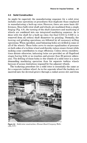
ferences. Since both rotor shaft and wheels are machined from a single
forging (Fig. 4.8), the turning of the shaft diameters and machining of
wheels are combined into one integrated machining sequence. As is
done with the shaft for a built-up rotor, the final 0.015 to 0.020 in is
removed from all critical shaft diameters by grinding. Normally, the
turning and grinding operations are followed by all necessary milling
operations. When specified, axial balancing holes are drilled in some or
all of the wheels. These holes serve to ensure equalization of pressure
on both sides of a turbine wheel and thereby reduce steam thrust while
making some contribution to stage efficiency. Unless stress considera-
tions dictate otherwise, balancing holes are provided on all flugelized
stages having little or no reaction and greater than 60 percent admis-
sion. The drilling of these holes in the wheels of a solid rotor is a more
demanding machining operation than for separate turbine wheels
because of access limitations imposed by the adjacent wheels.
The bucketing procedure for a solid rotor is essentially the same as
for a separate turbine wheel. As in the separate wheel the buckets are
inserted into the dovetail groove through a radial access slot and from
Figure 4.8 Solid rotor construction. (Dresser-Rand Company, Wells-
ville, N.Y.)