
Page 255 - Steam Turbines Design, Applications, and Rerating
P. 255
234 Chapter Twelve
■ The nozzle chest at the steam inlet provides flexibility and, in par-
ticular, short starting times (Fig. 12.14).
■ If necessary, separate fixed blade carriers are fitted to facilitate ther-
mal expansion (Fig. 12.15).
■ Welded rotor construction and its possible advantages have been dis-
cussed earlier. One-piece rotors can also be built for small machines.
■ Movable segments in the shaft seals at balance piston and casing
penetrations for the higher ratings.
■ Securely fixed control-stage blades, welded if necessary.
■ Reaction blading of rugged construction.
Reaction type mechanical drive turbines have been performing sat-
isfactorily for decades, proving the suitability of the design. This is fur-
ther supported by the fact that some of the largest mechanical drive
units in the world are the reaction type. A good example is the 50-MW
feedpump turbine for a 1350-MW Asea Brown-Boveri steam turbine at
a power generating plant in the United States that has been running
successfully since 1973. In the late 1970s several 100-MW compressor
drive turbines were put in service at Skikda, Algeria. They, and others
since then, have run without problems.
It should be noted that since the earliest days of the steam turbine
the impulse and reaction types of construction have existed side by
side. That neither has been able to supersede the other in any field of
application—whether for mechanical drives or power-generating
plants—implies that neither type is fundamentally better than the
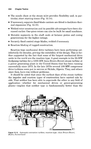
Figure 12.13 Automatic extraction turbine, reaction type. (Asea Brown-Boveri,
Baden, Switzerland)