
Page 259 - Steam Turbines Design, Applications, and Rerating
P. 259
238 Chapter Twelve
injection pumps presents a great hazard, especially at maximum injec-
tion rates. To guard against pump failure, untreated boiler feedwater is
used since these pumps are usually the most reliable in a plant.
If plant-operating conditions allow, the vacuum on a condensing tur-
bine should be reduced to 5 to 10 mmHg; for noncondensing turbines,
the exhaust pressure should be reduced to atmospheric pressure. Note
that on any noncondensing unit requiring full-speed washing, the
manufacturer should be consulted about minimum allowable exhaust
pressure. Extraction turbines should be run with the extraction line
shut off.
A steam gauge and thermometer should be installed between the
trip-throttle valve and the governor-controlled valves. The thermome-
ter should preferably be a recording type and should be very responsive
to small changes in temperature.
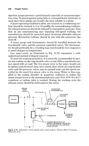
Low speed wash, as illustrated in Fig. 12.16, represents a well-
understood method of deposit removal.
To start the washing procedure, it is normally recommended to oper-
ate the turbine on the trip-throttle valve at one-fifth to one-fourth nor-
mal speed with no load. The live-steam valve to the mixer would now
be opened and the boiler stop valve closed, after which the trip-throttle
valve and the governor valves may be opened wide and the speed con-
trolled by the small live-steam valve to the mixer. Water is then sup-
plied to the mixing chamber in quantities sufficient to reduce the
steam temperature at the recommended rate until 10 to 15°F (6 to 9°C)
superheat at turbine inlet is reached. During the washing cycle the
exhaust steam should be discharged to the sewer.
Figure 12.16 Schematic of low-speed water wash system. (Dresser-Rand Company,
Wellsville, N.Y.)