
Page 89 - Steam Turbines Design, Applications, and Rerating
P. 89
70 Chapter Three
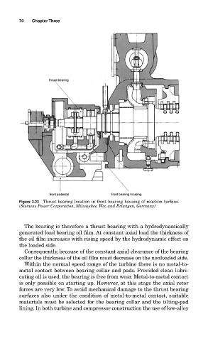
Figure 3.23 Thrust bearing location in front bearing housing of reaction turbine.
(Siemens Power Corporation, Milwaukee, Wis. and Erlangen, Germany)
The bearing is therefore a thrust bearing with a hydrodynamically
generated load bearing oil film. At constant axial load the thickness of
the oil film increases with rising speed by the hydrodynamic effect on
the loaded side.
Consequently, because of the constant axial clearance of the bearing
collar the thickness of the oil film must decrease on the nonloaded side.
Within the normal speed range of the turbine there is no metal-to-
metal contact between bearing collar and pads. Provided clean lubri-
cating oil is used, the bearing is free from wear. Metal-to-metal contact
is only possible on starting up. However, at this stage the axial rotor
forces are very low. To avoid mechanical damage to the thrust bearing
surfaces also under the condition of metal-to-metal contact, suitable
materials must be selected for the bearing collar and the tilting-pad
lining. In both turbine and compressor construction the use of low-alloy