
Page 90 - Steam Turbines Design, Applications, and Rerating
P. 90
Bearings for Mechanical Drive Turbines 71
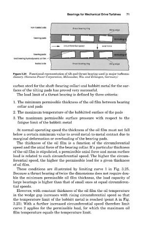
Figure 3.24 Functional representation of tilt-pad thrust bearing used in major turboma-
chinery. (Siemens Power Corporation, Milwaukee, Wis. and Erlangen, Germany)
carbon steel for the shaft (bearing collar) and babbitt metal for the sur-
faces of the tilting pads has proved very successful.
The load limit of a thrust bearing is defined by three criteria:
1. The minimum permissible thickness of the oil film between bearing
collar and pads
2. The maximum temperature of the babbitted surface of the pads
3. The maximum permissible surface pressure with respect to the
fatigue limit of the babbitt metal
At normal operating speed the thickness of the oil film must not fall
below a certain minimum value to avoid metal-to-metal contact due to
marginal deformation or overloading of the bearing pads.
The thickness of the oil film is a function of the circumferential
speed and the axial force of the bearing collar. If a particular thickness
of the oil film is stipulated, a permissible axial force and mean surface
load is related to each circumferential speed. The higher the circum-
ferential speed, the higher the permissible load for a given thickness
of oil film.
These conditions are illustrated by limiting curve 1 in Fig. 3.25.
Because a thrust bearing of twice the dimensions does not require dou-
ble the minimum permissible oil film thickness, the load capacity of
large bearings is higher than that of small ones at equal circumferen-
tial speeds.
However, with constant thickness of the oil film the oil temperature
in the wedge gap increases with rising circumferential speed so that
the temperature limit of the babbitt metal is reached (point A in Fig.
3.25). With a further increased circumferential speed therefore limit
curve 2 applies for the permissible load, for which the maximum oil
film temperature equals the temperature limit.