Page 132 - Structural Steel Designers Handbook AISC, AASHTO, AISI, ASTM, and ASCE-07 Design Standards
P. 132

Brockenbrough_Ch03.qxd  9/29/05  5:05 PM  Page 3.64


                                                        CONNECTIONS


                   3.64  CHAPTER THREE

                                                                   where f c ′ is the concrete compressive strength in
                                                                   ksi and

                                                                                1≤  A 2  ≤  2      (3.59)
                                                                                    A 1
                                                                   The required bearing strength is
                                                                                  f =  P           (3.60)
                                                                                   p
                                                                                      A 1
                                                                   where P is the factored column load in kips. In
                                                                   terms of these variables, the required base plate
                                                                   thickness is
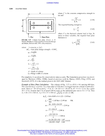
                               FIGURE 3.37 Column base plate. (Source:  A. R.
                               Tamboli, Handbook of Structural Steel Connection Design  t = l  f 2  p  (3.61)
                               and Details, McGraw-Hill, 1999, with permission.)  p   φ F y
                               where  l = max(m, n, λn′)
                                    φF y = base plate design strength = 0.90F y
                                     m =  N −095 d
                                           .
                                           2
                                      n =  B − 08 .  b f
                                           2
                                     n′ =  db f
                                          4
                                     λ  =  2  x  ≤1
                                        1  + 1 −  x
                                      x =  4 db f  f p
                                          +
                                            2
                                               F
                                         ( db f ) φ  cp
                                      d = depth of column
                                     b f = flange width of column
                               For simplicity, λ can always be conservatively taken as unity. The formulation given here was devel-
                               oped by Thornton (1990a, 1990b), based on previous work by Murray (1983), Fling (1970), and
                               Stockwell (1975). It is the method given in the 2005 AISC Manual.
                               Example of Base Plate Calculation.  The column of Fig. 3.37 is a W24 × 84 carrying 600 kips.
                               The concrete has f c ′= 4.0 ksi. Try a base plate of A36 steel, 4 in bigger than the column in both direc-
                               tions. Since d = 24.125 in and b f = 9 in, N = 24.125 + 4 = 28.125 in, B = 9 + 4 =13 in. Try a plate
                               28 × 13 in. Assume that 2 in of grout will be used, so the minimum pier size is 32 × 17 in. Thus
                                                                2
                                               2
                               A 1 = 28 × 13 = 364 in , A 2 = 32 × 17 = 544 in ,  AA/  1  = 1.22 < 2.  OK.
                                                                    2
                                                    φ F = 06 085 × ×122  = 249 ksi
                                                                  4
                                                                     .
                                                          .
                                                                          .
                                                            × .
                                                     cp
                                                      f =  600  = 165.   ksi  < 249.   ksi  OK
                                                       p
                                                          364
                                                      m =  28 − 0 95 24 125.  ×  .  = 254  in
                                                                          .
                                                                2
                                                       n =  13 − 0 8 9.  ×  = 290 in
                                                                     .
                                                             2
                                                             .
                                                      n′ =  24 125  × 9  = 368 in
                                                                     .
                                                              4
                                                                       .
                                                                 × .
                                                              .
                                                       x =  4  × 24 125 9 0 165  = 0..52

                                                          ( 24 125 + 9 0 . ) 2  249
                                                                       .
                                                            .
                           Downloaded from Digital Engineering Library @ McGraw-Hill (www.digitalengineeringlibrary.com)
                                      Copyright © 2004 The McGraw-Hill Companies. All rights reserved.
                                       Any use is subject to the Terms of Use as given at the website.
   127   128   129   130   131   132   133   134   135   136   137