
Page 135 - Structural Steel Designers Handbook AISC, AASHTO, AISI, ASTM, and ASCE-07 Design Standards
P. 135
Brockenbrough_Ch03.qxd 9/29/05 5:05 PM Page 3.67
CONNECTIONS
CONNECTIONS 3.67
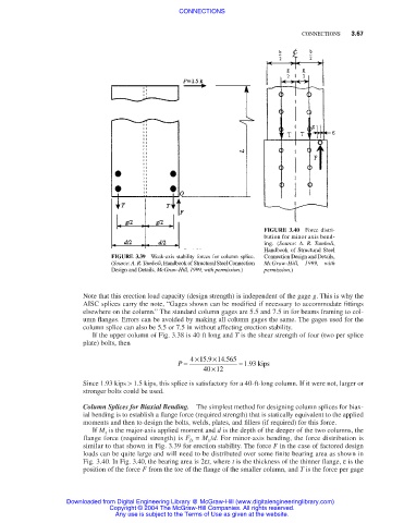
FIGURE 3.40 Force distri-
bution for minor axis bend-
ing. (Source: A. R. Tamboli,
Handbook of Structural Steel
FIGURE 3.39 Weak-axis stability forces for column splice. Connection Design and Details,
(Source: A. R. Tamboli, Handbook of Structural Steel Connection McGraw-Hill, 1999, with
Design and Details, McGraw-Hill, 1999, with permission.) permission.)
Note that this erection load capacity (design strength) is independent of the gage g. This is why the
AISC splices carry the note, “Gages shown can be modified if necessary to accommodate fittings
elsewhere on the column.” The standard column gages are 5.5 and 7.5 in for beams framing to col-
umn flanges. Errors can be avoided by making all column gages the same. The gages used for the
column splice can also be 5.5 or 7.5 in without affecting erection stability.
If the upper column of Fig. 3.38 is 40 ft long and T is the shear strength of four (two per splice
plate) bolts, then
.
P = 4 ×15 9 . ×14 565 = 193. kips
40 ×12
Since 1.93 kips > 1.5 kips, this splice is satisfactory for a 40-ft-long column. If it were not, larger or
stronger bolts could be used.
Column Splices for Biaxial Bending. The simplest method for designing column splices for biax-
ial bending is to establish a flange force (required strength) that is statically equivalent to the applied
moments and then to design the bolts, welds, plates, and fillers (if required) for this force.
If M x is the major-axis applied moment and d is the depth of the deeper of the two columns, the
flange force (required strength) is F fx = M x /d. For minor-axis bending, the force distribution is
similar to that shown in Fig. 3.39 for erection stability. The force F in the case of factored design
loads can be quite large and will need to be distributed over some finite bearing area as shown in
Fig. 3.40. In Fig. 3.40, the bearing area is 2εt, where t is the thickness of the thinner flange, ε is the
position of the force F from the toe of the flange of the smaller column, and T is the force per gage
Downloaded from Digital Engineering Library @ McGraw-Hill (www.digitalengineeringlibrary.com)
Copyright © 2004 The McGraw-Hill Companies. All rights reserved.
Any use is subject to the Terms of Use as given at the website.