
Page 133 - Structural Steel Designers Handbook AISC, AASHTO, AISI, ASTM, and ASCE-07 Design Standards
P. 133
Brockenbrough_Ch03.qxd 9/29/05 5:05 PM Page 3.65
CONNECTIONS
CONNECTIONS 3.65
.
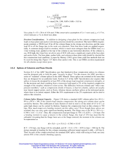
λ= 20 52 = 085
.
− .
1 + 1 0 52
., . , .
.
.
l = max( 254 290 085 × 368) = 313 in
× 65
21.
.
t p = 313 = 099 in
.
09 . × 36
Use a plate 1 × 13 × 28 in of A36 steel. If the conservative assumption of λ= 1 were used, t p = 1.17 in,
1
which indicates a 1 / 4-in-thick base plate.
Erection Considerations. In addition to designing a base plate for the column compression load,
loads on base plates and anchor rods during erection should be considered. The latest OSHA require-
ments postulate a 300-lb load 18 in off the column flange in the strong axis direction, and the same
load 18 in off the flange tips in the weak axis direction. Note that these loads are applied sequen-
tially. A common design load for erection, which is much more stringent than the OSHA load, is a
1-kip working load, applied at the top of the column in any horizontal direction. If the column is,
say, 40 ft high, this 1-kip force at a lever arm of 40 ft will cause a significant couple at the base plate
and anchor bolts. The base plate, anchor bolts, and column-to-base plate weld should be checked for
this construction load condition. A paper by Murray (1983) gives some yield line methods that can
be used for doing this. Figure 3.37 shows four anchor rods. This is an OSHA erection requirement
for all columns except minor posts.
3.5.3 Splices of Columns and Truss Chords
Section J1.4 of the AISC Specification says that finished-to-bear compression splices in columns
need be designed only to hold the parts “securely in place.” For this reason, the AISC provides a
series of “standard” column splices in the AISC Manual. These splices are nominal in the sense that
they are designed for no particular loads. Section J1.4 of the AISC Specification also requires that
splices in trusses be designed for at least 50% of the design load (required compression strength), or
for the moment and shear resulting from a transverse load equal to 2% of the required compressive
strength of the member, whichever is less severe. The difference between columns and “other com-
pression members,” such as compression chords of trusses, is that for columns, splices are usually
near lateral support points, such as floors, whereas trusses can have splices at the mid-panel point,
where there is no lateral support. Either the 50% requirement or the 2% requirement can be used to
address this situation.
Column Splice Moment Capacity. Figure 3.38 shows a standard AISC column splice for a W14 ×
99 to a W14 × 109. If the column load remains compression, the strong-axis column shear can be
carried by friction. The coefficient of static friction of steel to steel is of the order of 0.5 to 0.7, so
quite high shears can be carried by friction. Suppose the compression load on this column is 700
kips. How much major-axis bending moment can this splice carry? Even though these splices are
nominal, they can carry quite significant bending moment. The flange area of the W14 × 99 is A f =
2
0.780 × 14.6 = 11.4 in . Thus, the compression load per flange is 700 × 11.4/29.1 = 274 kips. For
a bending moment to cause a tension in the column flange, this load of 274 kips must first be
unloaded. Assuming that the flange force acts at the flange centroid, the moment in the column can
be represented as
M = T(d − t f ) = T(14.2 − 0.780) = 13.4T
If T = 274 kips, one flange will be unloaded, and M = 13.4 × 274 = 3670 in⋅kips = 306 kip⋅ft. The
design strength in bending for this column (assuming sufficient lateral support) is φM p = 649 kip⋅ft.
Thus, because of the compression load, the nominal AISC splice, while still seeing no load, can carry
almost 50% of the column’s bending capacity.
Downloaded from Digital Engineering Library @ McGraw-Hill (www.digitalengineeringlibrary.com)
Copyright © 2004 The McGraw-Hill Companies. All rights reserved.
Any use is subject to the Terms of Use as given at the website.