
Page 364 - Structural Steel Designers Handbook AISC, AASHTO, AISI, ASTM, and ASCE-07 Design Standards
P. 364
Brockenbrough_Ch08.qxd 9/29/05 5:21 PM Page 8.18
LATERAL-FORCE DESIGN
8.18 CHAPTER EIGHT
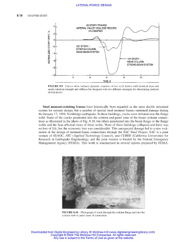
FIGURE 8.9 Curves show inelastic dynamic response of two steel frames with identical mass and
nearly identical strength and stiffness but designed with two different strategies for determining inelastic
deformations.
Steel moment-resisting frames have historically been regarded as the most ductile structural
system for seismic design, but a number of special steel moment frames sustained damage during
the January 17, 1994, Northridge earthquake. In these buildings, cracks were initiated near the flange
weld. Some of the cracks penetrated into the column and panel zone of the beam–column connec-
tions as illustrated in the photo of Fig. 8.10, but others penetrated into the beam flange or the flange
welds and the heat-affected zones of these welds. None of these buildings collapsed and there was
no loss of life, but the economic loss was considerable. This unexpected damage led to a new eval-
uation of the design of moment-frame connections through the SAC Steel Project. SAC is a joint
venture of SEAOC, ATC (Applied Technology Council), and CUREE (California Universities for
Research in Earthquake Engineering), and the joint venture is funded by the Federal Emergency
Management Agency (FEMA). This work is summarized in several reports prepared by FEMA.
FIGURE 8.10 Photograph of crack through the column flange and into the
column web or panel zone of connection.
Downloaded from Digital Engineering Library @ McGraw-Hill (www.digitalengineeringlibrary.com)
Copyright © 2004 The McGraw-Hill Companies. All rights reserved.
Any use is subject to the Terms of Use as given at the website.