
Page 81 - Structural Steel Designers Handbook AISC, AASHTO, AISI, ASTM, and ASCE-07 Design Standards
P. 81
Brockenbrough_Ch03.qxd 9/29/05 5:05 PM Page 3.13
CONNECTIONS
CONNECTIONS 3.13
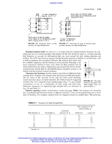
FIGURE 3.6 Staggered holes provide FIGURE 3.7 Increasing the gage in framing angles
clearance for high-strength bolts. provides clearance for high-strength bolts.
1
Standard fastener holes for bolts are / 16 in larger than the nominal fastener diameter. In com-
1
puting net area of a tension member, the diameter of the hole should be taken / 16 in larger than the
hole diameter, to account for deformation that can occur around the hole during punching and
drilling. The AISC Specification requires that the holes be punched or drilled, or cut thermally, with
a surface roughness not exceeding 1000 µin. The method used varies with
the available equipment and the thickness of the material. Punching is the
most economical method in many cases. Holes for thick material may be
either drilled from the solid or subpunched and reamed. The die for all sub-
1
punched holes and the drill for all subdrilled holes should be at least / 16 in
smaller than the nominal fastener diameter.
Clearance for fasteners must be ample to provide for tightening high-
strength bolts. Detailers who prepare shop drawings for fabricators gener-
ally are aware of the necessity of this and can, with careful detailing,
secure necessary space. In tight situations, the solution may be staggering
FIGURE 3.8 The usual
of holes (Fig. 3.6), variations from standard gages (Fig. 3.7), use of knife
minimum clearances A for
connections, or use of a combination of shop welds and field bolts. high-strength bolts are
Minimum clearances for tightening high-strength bolts are indicated in given in Table 3.1.
Fig. 3.8 and Table 3.1.
Fastener spacing includes consideration of pitch and gage. Pitch is the distance (in) along the
line of principal load between centers of adjacent fasteners. It may be measured along one or more
lines of fasteners. For example, suppose bolts are staggered along two parallel lines. The pitch may
TABLE 3.1 Clearances for High-Strength Bolts
Min. clearance A* for
twist-off bolts, in
Usual min.
Bolt diameter, in Nut height, in clearance A*, in Small tool Large tool
5 5 1 5 —
/ 8 / 8 1 / 8
3 3 1 5 7
/ 4 / 4 1 / 4 1 / 8 1 / 8
7 7 3 5 7
/ 8 / 8 1 / 8 1 / 8 1 / 8
7
7
1 1 1 / 16 — 1 / 8
1 1 9 — —
1 / 8 1 / 8 1 / 16
1 1 11 — —
1 / 4 1 / 4 1 / 16
*See Fig. 3.8.
Downloaded from Digital Engineering Library @ McGraw-Hill (www.digitalengineeringlibrary.com)
Copyright © 2004 The McGraw-Hill Companies. All rights reserved.
Any use is subject to the Terms of Use as given at the website.