
Page 85 - Structural Steel Designers Handbook AISC, AASHTO, AISI, ASTM, and ASCE-07 Design Standards
P. 85
Brockenbrough_Ch03.qxd 9/29/05 5:05 PM Page 3.17
CONNECTIONS
CONNECTIONS 3.17
The AISC Specification defines the conditions for item 1 as
1. Column splices in all tier structures 125 ft or more in height
2. Connections of all beams and girders to columns and any other beams and girders on which the
bracing of columns is dependent, in structures over 125 ft in height
3. In all structures carrying cranes of over 5-ton capacity, roof truss splices and connections of trusses
to columns, column splices, column bracing, knee braces, and crane supports
4. Connections for supports of running machinery, or of other live loads which produce impact or
reversal of stress
Fully tensioned bolts can be installed using four different methods: calibrated wrench, turn-of-nut,
as twist-off-type tension-control bolts, or with direct-tension indicators. In all installation methods,
the plies are first brought together as in a snug-tight condition, before tensioning begins. Bolts should
be tensioned starting with the most rigid element and moving to the most flexible element, to minimize
relaxation in the previously tensioned bolts. The calibrated-wrench method is a torque-controlled
method, in which the wrench is calibrated to stop torquing after the required tension is achieved in
the bolt. An ASTM F436 washer must be used under the turned element, and the unturned element
must be prevented from turning. The wrench should be set to cut off at 5% above the required tension.
Because the torque-controlled methods of installation rely on so many variables for proper performance,
it is imperative that the wrench be calibrated at least daily, and also when changes occur in the bolting
setup such as changes in bolt diameter, hose length, or number of wrenches run off the same air supply.
It is also important that fasteners be kept protected from dirt and moisture to ensure that the proper
tension is achieved.
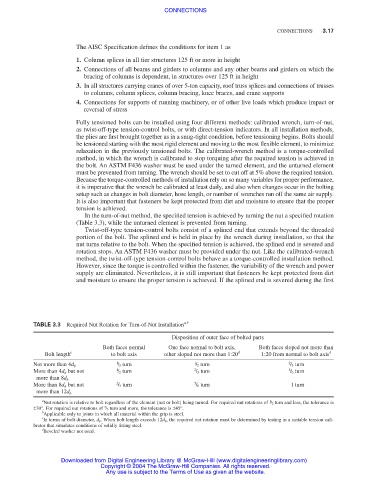
In the turn-of-nut method, the specified tension is achieved by turning the nut a specified rotation
(Table 3.3), while the unturned element is prevented from turning.
Twist-off-type tension-control bolts consist of a splined end that extends beyond the threaded
portion of the bolt. The splined end is held in place by the wrench during installation, so that the
nut turns relative to the bolt. When the specified tension is achieved, the splined end is severed and
rotation stops. An ASTM F436 washer must be provided under the nut. Like the calibrated-wrench
method, the twist-off-type tension-control bolts behave as a torque-controlled installation method.
However, since the torque is controlled within the fastener, the variability of the wrench and power
supply are eliminated. Nevertheless, it is still important that fasteners be kept protected from dirt
and moisture to ensure the proper tension is achieved. If the splined end is severed during the first
TABLE 3.3 Required Nut Rotation for Turn-of-Nut Installation a,b
Disposition of outer face of bolted parts
Both faces normal One face normal to bolt axis, Both faces sloped not more than
Bolt length c to bolt axis other sloped not more than 1:20 d 1:20 from normal to bolt axis d
1 / 3 turn 1 / 2 turn 2 / 3 turn
Not more than 4d b
More than 4d b but not 1 / 2 turn 2 / 3 turn 5 / 6 turn
more than 8d b
More than 8d b but not 2 / 3 turn 5 / 6 turn 1 turn
more than 12d b
a
Nut rotation is relative to bolt regardless of the element (nut or bolt) being turned. For required nut rotations of / 2 turn and less, the tolerance is
1
2
±30°. For required nut rotations of / 3 turn and more, the tolerance is ±45°.
b
Applicable only to joints in which all material within the grip is steel.
c
In terms of bolt diameter, d b . When bolt length exceeds 12d b , the required nut rotation must be determined by testing in a suitable tension cali-
brator that simulates conditions of solidly fitting steel.
d
Beveled washer not used.
Downloaded from Digital Engineering Library @ McGraw-Hill (www.digitalengineeringlibrary.com)
Copyright © 2004 The McGraw-Hill Companies. All rights reserved.
Any use is subject to the Terms of Use as given at the website.