
Page 82 - Structural Steel Designers Handbook AISC, AASHTO, AISI, ASTM, and ASCE-07 Design Standards
P. 82
Brockenbrough_Ch03.qxd 9/29/05 5:05 PM Page 3.14
CONNECTIONS
3.14 CHAPTER THREE
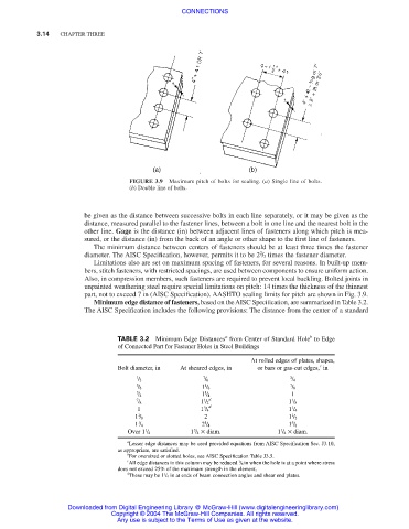
FIGURE 3.9 Maximum pitch of bolts for sealing. (a) Single line of bolts.
(b) Double line of bolts.
be given as the distance between successive bolts in each line separately, or it may be given as the
distance, measured parallel to the fastener lines, between a bolt in one line and the nearest bolt in the
other line. Gage is the distance (in) between adjacent lines of fasteners along which pitch is mea-
sured, or the distance (in) from the back of an angle or other shape to the first line of fasteners.
The minimum distance between centers of fasteners should be at least three times the fastener
2
diameter. The AISC Specification, however, permits it to be 2 / 3 times the fastener diameter.
Limitations also are set on maximum spacing of fasteners, for several reasons. In built-up mem-
bers, stitch fasteners, with restricted spacings, are used between components to ensure uniform action.
Also, in compression members, such fasteners are required to prevent local buckling. Bolted joints in
unpainted weathering steel require special limitations on pitch: 14 times the thickness of the thinnest
part, not to exceed 7 in (AISC Specification). AASHTO sealing limits for pitch are shown in Fig. 3.9.
Minimum edge distance of fasteners, based on the AISC Specification, are summarized in Table 3.2.
The AISC Specification includes the following provisions: The distance from the center of a standard
a
b
TABLE 3.2 Minimum Edge Distances from Center of Standard Hole to Edge
of Connected Part for Fastener Holes in Steel Buildings
At rolled edges of plates, shapes,
c
Bolt diameter, in At sheared edges, in or bars or gas-cut edges, in
1 7 3
/ 2 / 8 / 4
5 1 7
/ 8 1 / 8 / 8
3 1 1
/ 4 1 / 4
7 1 d 1
/ 8 1 / 2 1 / 8
3 d
1
1 1 / 4 1 / 4
1 2 1
1 / 8 1 / 2
1 1 5
1 / 4 2 / 4 1 / 8
1
1 1 / 4 × diam. 1 / 4 × diam.
3
Over 1 / 4
a
Lesser edge distances may be used provided equations from AISC Specification Sec. J3.10,
as appropriate, are satisfied.
b
For oversized or slotted holes, see AISC Specification Table J3.5.
c
1
All edge distances in this column may be reduced / 8 in when the hole is at a point where stress
does not exceed 25% of the maximum strength in the element.
d
1
These may be 1 / 4 in at ends of beam connection angles and shear end plates.
Downloaded from Digital Engineering Library @ McGraw-Hill (www.digitalengineeringlibrary.com)
Copyright © 2004 The McGraw-Hill Companies. All rights reserved.
Any use is subject to the Terms of Use as given at the website.