
Page 87 - Structural Steel Designers Handbook AISC, AASHTO, AISI, ASTM, and ASCE-07 Design Standards
P. 87
Brockenbrough_Ch03.qxd 9/29/05 5:05 PM Page 3.19
CONNECTIONS
CONNECTIONS 3.19
Items 1, 2, and 3 are quantitative. Item 4 is qualitative and requires judgment. The previous two para-
graphs are provided to aid that judgment. Slip in most structures that are not covered by items 1, 2,
and 3 is rarely a concern. Specifying slip-critical connections where bearing connections would suf-
fice leads to uneconomical designs, usually with no accompanying increase in the overall safety of
the structure.
It should be noted that wind and seismic loads do not produce fatigue loads that would require
the use of slip-critical connections. The AISC Specification states that “Fatigue need not be consid-
ered for seismic effects or for the effects of wind loading on normal building lateral force-resisting
systems and building enclosure components.” This is because most such load changes occur only a
small number of times or produce only minor stress fluctuations. The occurrence of full design wind
or earthquake loads is too infrequent to warrant consideration in fatigue design. On the other hand,
crane runways and supporting structures for machinery and equipment are often subjected to fatigue
loading conditions.
3.2.7 Threads-Included and Threads-Excluded Conditions
Bolts in bearing can be designed either assuming that the shear plane passes through the threads
(threads included or N type) or that the shear plane does not pass through the threads (threads excluded
or X type). It is commonly perceived that special detailing and field installation are required to assure
a threads-excluded condition. Though this is true when connecting thin material, it is not true when
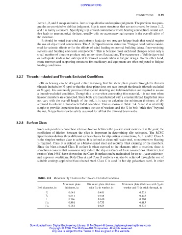
heavier members are connected. Since bolts are manufactured with a constant thread length that does
not vary with the overall length of the bolt, it is easy to calculate the minimum thickness of ply
required to achieve a threads-excluded condition. This is shown in Table 3.4. Since it is relatively
1
simple to provide inspection that ensures the use of washers and the / 4-in bolt “stick-thru” beyond
the nut, X-type bolts can be safely assumed for all but the thinnest beam webs.
3.2.8 Surface Class
Since a slip-critical connection relies on friction between the plies to resist movement at the joint, the
coefficient of friction between the plies is important in determining slip resistance. The RCSC
Specification defines three different surface classes for slip-critical connections, A, B, and C. Class A
is the simplest surface class to achieve. It is defined as clean mill-scale steel, so no extensive blasting
is required. Class B is defined as a blast-cleaned steel and requires blast cleaning of the members.
Since the blast-cleaned Class B surface is often exposed to the elements prior to erection, there is
sometimes concern that corrosion may reduce the slip resistance of these connections. However, test
results (Yura 1981) have shown that the Class B surface can be maintained for up to 1 year under nor-
mal exposure conditions. Both Class A and Class B surfaces can also be achieved through the use of
suitable coatings applied to blast-cleaned steel. Class C is used for hot-dip galvanized steel. In order
TABLE 3.4 Minimum Ply Thickness for Threads-Excluded Condition
Minimum plate Minimum plate thickness Minimum plate thickness with / 32-in
5
5
1
Bolt diameter, in thickness, in with / 32-in washer, in washer and / 4-in stick-through, in
3 0.641 0.485 0.235
/ 4
7 0.641 0.485 0.235
/ 8
1 0.766 0.610 0.360
1 0.891 0.735 0.485
1 / 8
1
1 / 4 0.781 0.625 0.375
Downloaded from Digital Engineering Library @ McGraw-Hill (www.digitalengineeringlibrary.com)
Copyright © 2004 The McGraw-Hill Companies. All rights reserved.
Any use is subject to the Terms of Use as given at the website.