
Page 89 - Structural Steel Designers Handbook AISC, AASHTO, AISI, ASTM, and ASCE-07 Design Standards
P. 89
Brockenbrough_Ch03.qxd 9/29/05 5:05 PM Page 3.21
CONNECTIONS
CONNECTIONS 3.21
TABLE 3.6 Minimum Weld and Base-Metal Dimensions for
Threaded Welded Studs*
Stud size, in Dimension A, in Dimensions B and C, in
5 1 1
/ 8 / 8 / 4
3 3 5
/ 4 / 16 / 16
7 3 3
/ 8 / 16 / 8
1 1 / 4 7 / 16
*Dimensions A, B, and C are shown in Fig. 3.12.
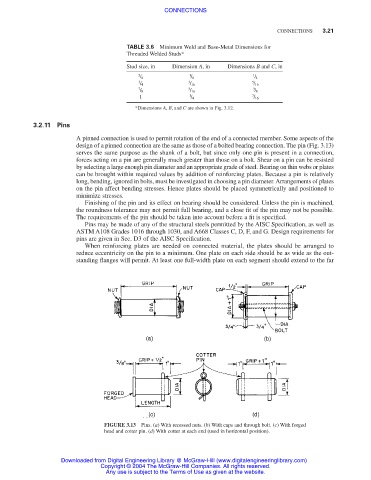
3.2.11 Pins
A pinned connection is used to permit rotation of the end of a connected member. Some aspects of the
design of a pinned connection are the same as those of a bolted bearing connection. The pin (Fig. 3.13)
serves the same purpose as the shank of a bolt, but since only one pin is present in a connection,
forces acting on a pin are generally much greater than those on a bolt. Shear on a pin can be resisted
by selecting a large enough pin diameter and an appropriate grade of steel. Bearing on thin webs or plates
can be brought within required values by addition of reinforcing plates. Because a pin is relatively
long, bending, ignored in bolts, must be investigated in choosing a pin diameter. Arrangements of plates
on the pin affect bending stresses. Hence plates should be placed symmetrically and positioned to
minimize stresses.
Finishing of the pin and its effect on bearing should be considered. Unless the pin is machined,
the roundness tolerance may not permit full bearing, and a close fit of the pin may not be possible.
The requirements of the pin should be taken into account before a fit is specified.
Pins may be made of any of the structural steels permitted by the AISC Specification, as well as
ASTM A108 Grades 1016 through 1030, and A668 Classes C, D, F, and G. Design requirements for
pins are given in Sec. D3 of the AISC Specification.
When reinforcing plates are needed on connected material, the plates should be arranged to
reduce eccentricity on the pin to a minimum. One plate on each side should be as wide as the out-
standing flanges will permit. At least one full-width plate on each segment should extend to the far
FIGURE 3.13 Pins. (a) With recessed nuts. (b) With caps and through bolt. (c) With forged
head and cotter pin. (d) With cotter at each end (used in horizontal position).
Downloaded from Digital Engineering Library @ McGraw-Hill (www.digitalengineeringlibrary.com)
Copyright © 2004 The McGraw-Hill Companies. All rights reserved.
Any use is subject to the Terms of Use as given at the website.