
Page 330 - Structural Steel Designers Handbook AISC, AASHTO, AISI, ASTM, and ASCE-07 Design Standards
P. 330
Brockenbrough_Ch07.qxd 9/29/05 5:17 PM Page 7.14
FLOOR AND ROOF SYSTEMS
7.14 CHAPTER SEVEN
In general, wide-flange shapes are readily available in several grades of steel. Currently, the preferred
material specification for wide-flange shapes is ASTM A992, having a minimum yield strength of
50 ksi and a minimum tensile strength of 65 ksi, rather than the previously used designations of
ASTM A36 and ASTM A572 Grade 50. Higher strengths can be obtained by specifying ASTM A572
Grade 60 or 65, or ASTM A913 Grade 60, 65, or 70. Other ASTM designations and grades of steel
are also available, though less commonly used.
Interfacing with mechanical ductwork is usually accomplished in one of two ways. First, the steel
framing can be designed to incorporate the shallowest members that provide the required strength
and stiffness, and the mechanical ductwork can be routed beneath the floor framing. As an alterna-
tive, deeper beams and girders than would otherwise be necessary can be used, and these members
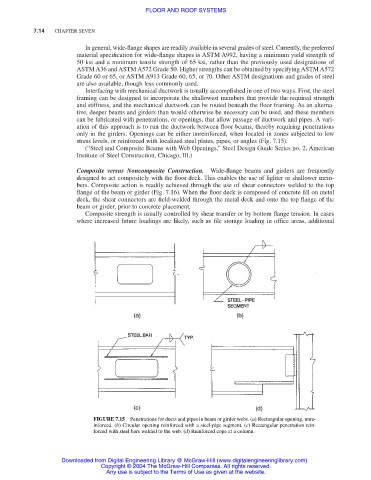
can be fabricated with penetrations, or openings, that allow passage of ductwork and pipes. A vari-
ation of this approach is to run the ductwork between floor beams, thereby requiring penetrations
only in the girders. Openings can be either unreinforced, when located in zones subjected to low
stress levels, or reinforced with localized steel plates, pipes, or angles (Fig. 7.15).
(“Steel and Composite Beams with Web Openings,” Steel Design Guide Series no. 2, American
Institute of Steel Construction, Chicago, Ill.)
Composite versus Noncomposite Construction. Wide-flange beams and girders are frequently
designed to act compositely with the floor deck. This enables the use of lighter or shallower mem-
bers. Composite action is readily achieved through the use of shear connectors welded to the top
flange of the beam or girder (Fig. 7.16). When the floor deck is composed of concrete fill on metal
deck, the shear connectors are field-welded through the metal deck and onto the top flange of the
beam or girder, prior to concrete placement.
Composite strength is usually controlled by shear transfer or by bottom flange tension. In cases
where increased future loadings are likely, such as file storage loading in office areas, additional
FIGURE 7.15 Penetrations for ducts and pipes in beam or girder webs. (a) Rectangular opening, unre-
inforced. (b) Circular opening reinforced with a steel-pipe segment. (c) Rectangular penetration rein-
forced with steel bars welded to the web. (d) Reinforced cope at a column.
Downloaded from Digital Engineering Library @ McGraw-Hill (www.digitalengineeringlibrary.com)
Copyright © 2004 The McGraw-Hill Companies. All rights reserved.
Any use is subject to the Terms of Use as given at the website.