
Page 122 - Sustainability in the Process Industry Integration and Optimization
P. 122
P r o c e s s I n t e g r a t i o n f o r I m p r ov i n g E n e r g y E f f i c i e n c y 99
as unaccountable steam usage. These additional requirements have
to be considered when analyzing or designing the site’s utility
system. Such steam demands are considered to be sink elements
and are added to the Site Sink Profile without any temperature
correction.
4.6.3 Heat Recovery via the Steam System
The maximum possible heat recovery through a utility system can be
targeted by using the Site Sink and Source Profiles in combination
with the steam header saturation temperatures. Source CCs for utility
generation and usage are constructed that account for feasible heat
transfer from the Site Source Profile to the site source CC and from
the site sink CC to the Site Sink Profile. The site CCs are analogous to
the individual process CCs. The source CC is built starting from the
highest feasible steam level. The steam generation at each level is
maximized before the next lower levels are analyzed. This ensures
maximum utilization of the heat sources’ temperature potential. The
remainder of the Site Source Profile (i.e., the part that does not overlap
the newly built source CC) is served by CW. Building the sink CC
follows a symmetrical procedure only starting from the lowest
possible steam level. The use of this level is maximized before moving
up to the next higher temperature level, and so forth until steam with
the highest possible level is used—including boiler-generated
steam.
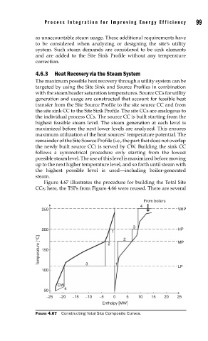
Figure 4.67 illustrates the procedure for building the Total Site
CCs; here, the TSPs from Figure 4.66 were reused. There are several
From boilers
4
250 VHP
3
200 HP
1 2
Temperature [°C] 150 2 MP
3
1
LP
100
CW
4
50
−25 −20 −15 −10 −5 0 5 10 15 20 25
Enthalpy [MW]
FIGURE 4.67 Constructing Total Site Composite Curves.