
Page 121 - Sustainability in the Process Industry Integration and Optimization
P. 121
98 Cha p te r F o u r
Shifed – T **
T **
Temperature T * T *
PINCH
Shifed – T **
1.1. Remove the pockets
1.2. Shift
ΔH ΔH
1. Extract segments 2. Rotate source segments
T ** T **
0 ΔH
0 ΔH
3. Combine segments
4. Align profiles
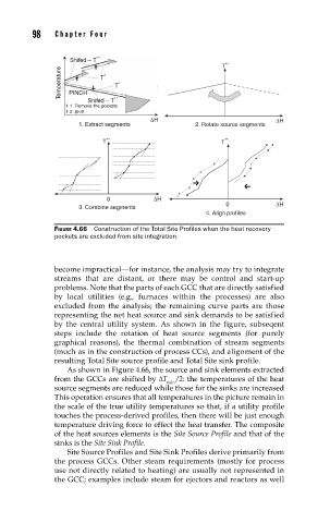
FIGURE 4.66 Construction of the Total Site Profi les when the heat recovery
pockets are excluded from site integration.
become impractical—for instance, the analysis may try to integrate
streams that are distant, or there may be control and start-up
problems. Note that the parts of each GCC that are directly satisfied
by local utilities (e.g., furnaces within the processes) are also
excluded from the analysis; the remaining curve parts are those
representing the net heat source and sink demands to be satisfied
by the central utility system. As shown in the figure, subseqent
steps include the rotation of heat source segments (for purely
graphical reasons), the thermal combination of stream segments
(much as in the construction of process CCs), and alignment of the
resulting Total Site source profile and Total Site sink profile.
As shown in Figure 4.66, the source and sink elements extracted
from the GCCs are shifted by ΔT /2: the temperatures of the heat
min
source segments are reduced while those for the sinks are increased
This operation ensures that all temperatures in the picture remain in
the scale of the true utility temperatures so that, if a utility profile
touches the process-derived profiles, then there will be just enough
temperature driving force to effect the heat transfer. The composite
of the heat sources elements is the Site Source Profile and that of the
sinks is the Site Sink Profile.
Site Source Profiles and Site Sink Profiles derive primarily from
the process GCCs. Other steam requirements (mostly for process
use not directly related to heating) are usually not represented in
the GCC; examples include steam for ejectors and reactors as well