
Page 116 - Sustainability in the Process Industry Integration and Optimization
P. 116
P r o c e s s I n t e g r a t i o n f o r I m p r ov i n g E n e r g y E f f i c i e n c y 93
typically introduces loops into the final topology and leads to larger
number of heat exchanger units. The final step in HEN design is
evolution of the topology: identifying heat load loops and open heat
load paths; then using them to optimize the network in terms of heat
loads, heat transfer area, and topology. During this phase, formerly
rigorous requirements—for example, that all temperature differences
exceed ΔT and that cross-Pinch heat transfers be excluded—are
min
usually relaxed. The resulting optimization formulations are typically
nonlinear and involve structural decisions, so they are MINLP
problems. Different approximations and simplifying assumptions
can be introduced to obtain linear and/or continuous formulations.
The design evolution step can even be performed manually by
breaking the loops and reducing the number of heat exchangers.
Eliminating heat exchangers from the topology is done at the expense
of shifting heat loads (from the eliminated heat recovery exchangers)
to utility exchangers: heaters and coolers. Topology evolution
terminates when the resulting energy cost increase exceeds the
projected savings in capital costs, which corresponds to a total cost
minimum.
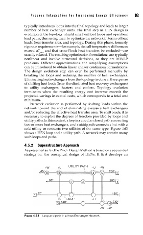
Network evolution is performed by shifting loads within the
network toward the end of eliminating excessive heat exchangers
and/or reducing the effective heat transfer area. To shift loads, it is
necessary to exploit the degrees of freedom provided by loops and
utility paths. In this context, a loop is a circular closed path connecting
two or more heat exchangers, and a utility path connects a hot with a
cold utility or connects two utilities of the same type. Figure 4.63
shows a HEN loop and a utility path. A network may contain many
such loops and paths.
4.5.2 Superstructure Approach
As presented so far, the Pinch Design Method is based on a sequential
strategy for the conceptual design of HENs. It first develops an
UTILITY PATH
+W +U −U −W
40° 250°
C 1 4 5 2
80° 200°
2 3 4
20° 180°
1
+U LOOP −U
140° 230°
3 H
−W +W
FIGURE 4.63 Loop and path in a Heat Exchanger Network.