
Page 115 - Sustainability in the Process Industry Integration and Optimization
P. 115
92 Cha p te r F o u r
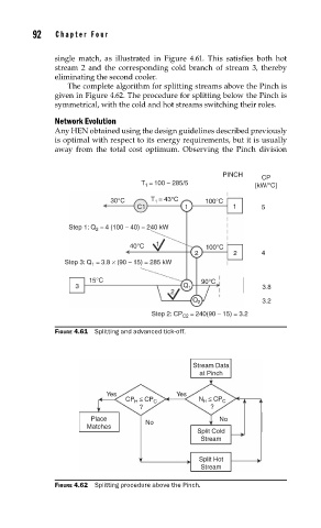
single match, as illustrated in Figure 4.61. This satisfies both hot
stream 2 and the corresponding cold branch of stream 3, thereby
eliminating the second cooler.
The complete algorithm for splitting streams above the Pinch is
given in Figure 4.62. The procedure for splitting below the Pinch is
symmetrical, with the cold and hot streams switching their roles.
Network Evolution
Any HEN obtained using the design guidelines described previously
is optimal with respect to its energy requirements, but it is usually
away from the total cost optimum. Observing the Pinch division
PINCH
CP
= 100 − 285/5
T 1 [kW/°C]
30°C T = 43°C 100°C
1
C1 1 1 5
Step 1: Q 2 = 4 (100 − 40) = 240 kW
40°C 1 100°C
2 2 4
Step 3: Q = 3.8 × (90 − 15) = 285 kW
1
15°C 90°C
3 Q 1 3.8
2
Q 2 3.2
Step 2: CP = 240(90 − 15) = 3.2
C2
FIGURE 4.61 Splitting and advanced tick-off.
Stream Data
at Pinch
Yes Yes
CP ≤ CP C N ≤ CP C
H
H
? ?
Place No
Matches No
Split Cold
Stream
Split Hot
Stream
FIGURE 4.62 Splitting procedure above the Pinch.