
Page 111 - Sustainability in the Process Industry Integration and Optimization
P. 111
88 Cha p te r F o u r
CP Q STREAM
[kW/°C] [kW]
150°C
203.3°C 250°C
2 15 1500
150°C 200°C
4 25 1250
140°C 180°C
1 20 800
800 kW
140°C T X = 181.7°C 205°C 230°C
3 H 30 2700
1250 kW 700 kW 750 kW
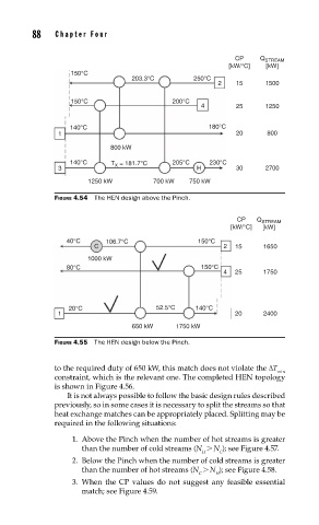
FIGURE 4.54 The HEN design above the Pinch.
CP Q STREAM
[kW/°C] [kW]
40°C 106.7°C 150°C
C 2 15 1650
1000 kW
80°C 150°C
4 25 1750
20°C 52.5°C 140°C
1 20 2400
650 kW 1750 kW
FIGURE 4.55 The HEN design below the Pinch.
to the required duty of 650 kW, this match does not violate the ΔT
min
constraint, which is the relevant one. The completed HEN topology
is shown in Figure 4.56.
It is not always possible to follow the basic design rules described
previously, so in some cases it is necessary to split the streams so that
heat exchange matches can be appropriately placed. Splitting may be
required in the following situations:
1. Above the Pinch when the number of hot streams is greater
than the number of cold streams (N > N ); see Figure 4.57.
H C
2. Below the Pinch when the number of cold streams is greater
than the number of hot streams (N > N ); see Figure 4.58.
C H
3. When the CP values do not suggest any feasible essential
match; see Figure 4.59.