Page 222 -
P. 222

chaPter 7  •  Using Data Flow Diagrams     189


                                                     Logical Data Flow Diagram


                          Customer            D1     Prices                                            Customer


                              Items to                 Prices                                      Payment
                              Purchase                                                                     Receipt

                            1                         2                         3                        4
                                                                                                        Settle
                          Identify    Item ID       Look Up  Items and Prices  Compute  Amount to Be Paid  Transaction
                                                                               Total
                           Item                     Prices                    Cost of                  and Issue
                                                                              Order                    Receipt


                                                      Physical Data Flow Diagram


                          Customer            D1   UPC Price File       D2   Temporary                 Customer
                                                                             Trans. File

                             Items Brought    UPC Code  Item Description  Items and  Items, Prices,  Cash, Check,
                                                                         Prices
                             to Checkout                and Prices                and Subtotals  or Debit Card  Cash Register
                                                                                                           Receipt
                            1                         2                         3                        4
                                                                                         Calculated
                           Pass    UPC Bar Code     Look Up  Item Codes and Prices     Amount to Be Paid  Collect Money
                         Items Over                Code and                  Compute                   and Give
                          Scanner                    Price                     Total                   Receipt
                         (Manual)                   in File                    Cost                    (Manual)
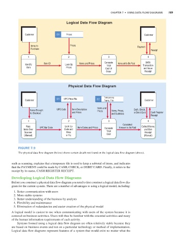


                      Figure 7.9
                      The physical data flow diagram (below) shows certain details not found on the logical data flow diagram (above).


                 such as scanning, explains that a temporary file is used to keep a subtotal of items, and indicates
                 that the PAYMENT could be made by CASH, CHECK, or DEBIT CARD. Finally, it refers to the
                 receipt by its name, CASH REGISTER RECEIPT.

                 Developing Logical Data Flow Diagrams
                 Before you construct a physical data flow diagram you need to first construct a logical data flow dia-
                 gram for the current system. There are a number of advantages to using a logical model, including:
                   1. Better communication with users
                   2. More stable systems
                   3. Better understanding of the business by analysts
                   4. Flexibility and maintenance
                   5. Elimination of redundancies and easier creation of the physical model

                 A logical model is easiest to use when communicating with users of the system because it is
                 centered on business activities. Users will thus be familiar with the essential activities and many
                 of the human information requirements of each activity.
                     Systems formed using a logical data flow diagram are often relatively stable because they
                 are based on business events and not on a particular technology or method of implementation.
                 Logical data flow diagrams represent features of a system that would exist no matter what the
   217   218   219   220   221   222   223   224   225   226   227