
Page 218 -
P. 218
chaPter 7 • Using Data Flow Diagrams 185
D1 Data Store 1
Record A Matching data flow.
3 4
Entity Input B General Data Flow D General
2 Process Process
CCC DDD
Data flow from
parent process to D1 Data Store 1
child diagram must
match.
Record A
3.1 3.2
Transaction Transaction
Input B Detailed Record 1 D5 Transaction Record 1 Detailed
Process File 1 Process
XXX YYY
Error Detailed
Data Flow Z
Transaction files 3.3
may be added to
Error lines may be lower-level diagrams.
added on a detailed Detailed
child diagram. Process
ZZZ
Output flow must
match the parent Data Flow D
process.
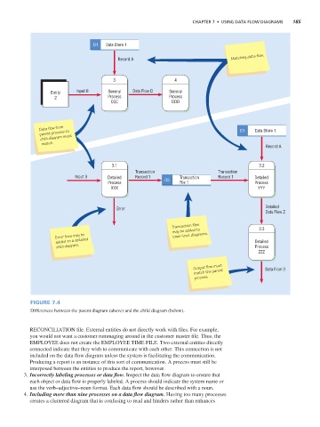
Figure 7.4
Differences between the parent diagram (above) and the child diagram (below).
RECONCILIATION file. External entities do not directly work with files. For example,
you would not want a customer rummaging around in the customer master file. Thus, the
EMPLOYEE does not create the EMPLOYEE TIME FILE. Two external entities directly
connected indicate that they wish to communicate with each other. This connection is not
included on the data flow diagram unless the system is facilitating the communication.
Producing a report is an instance of this sort of communication. A process must still be
interposed between the entities to produce the report, however.
3. Incorrectly labeling processes or data flow. Inspect the data flow diagram to ensure that
each object or data flow is properly labeled. A process should indicate the system name or
use the verb–adjective–noun format. Each data flow should be described with a noun.
4. Including more than nine processes on a data flow diagram. Having too many processes
creates a cluttered diagram that is confusing to read and hinders rather than enhances