
Page 219 -
P. 219
186 Part 3 • the analysis Process
Process 2 has no
Employee input. The Gross
Employee D1 Master Pay data flow is
Process 1 has going in the wrong
direction.
Employee no output.
Record
Hours
Worked
1 2 3
Employee
D2 Employee Time Record Calculate Gross Pay Calculate Withholding Calculate
Time File Gross Withholding Net Pay
Pay Amount
Net
Pay
An external entity 4
should not directly
connect to a data Employee
store. Employee Record Print
D1
Master Employee
Paycheck
A data store should Check
not directly connect Employee
to another data Reconciliation Paycheck
store. Record
Check
D3 Employee
Reconciliation
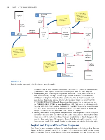
Figure 7.5
Typical errors that can occur in a data flow diagram (payroll example).
communication. If more than nine processes are involved in a system, group some of the
processes that work together into a subsystem and place them in a child diagram.
5. Omitting data flow. Examine your diagram for linear flow—that is, data flow in which
each process has only one input and one output. Except in the case of very detailed
child data flow diagrams, linear data flow is somewhat rare. Its presence usually indi-
cates that the diagram has missing data flow. For instance, the process CALCULATE
WITHHOLDING AMOUNT needs the number of dependents that an employee has and
the WITHHOLDING RATES as input. In addition, NET PAY cannot be calculated solely
from the WITHHOLDING, and the EMPLOYEE PAYCHECK cannot be created from the
NET PAY alone; it also needs to include an EMPLOYEE NAME, as well as the current
and year-to-date payroll and WITHHOLDING AMOUNT figures.
6. Creating unbalanced decomposition (or explosion) in child diagrams. Each child diagram
should have the same input and output data flow as the parent process. An exception to this
rule is minor output, such as error lines, which are included only on the child diagram. The
data flow diagram in Figure 7.6 is correctly drawn. Note that although the data flow is not
linear, you can clearly follow a path directly from the source entity to the destination entity.
Logical and Physical Data Flow Diagrams
Data flow diagrams are categorized as either logical or physical. A logical data flow diagram
focuses on the business and how the business operates. It is not concerned with how the system
will be constructed. Instead, it describes the business events that take place and the data required