
Page 172 - Tandem Techniques
P. 172
Page 155
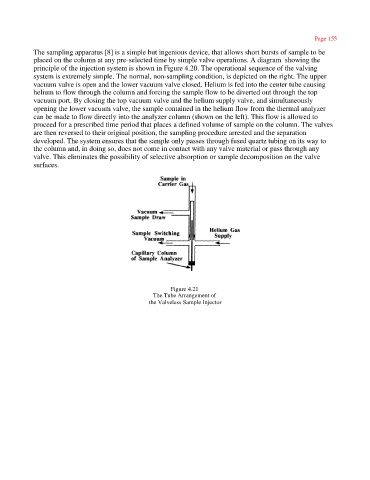
The sampling apparatus [8] is a simple but ingenious device, that allows short bursts of sample to be
placed on the column at any pre-selected time by simple valve operations. A diagram showing the
principle of the injection system is shown in Figure 4.20. The operational sequence of the valving
system is extremely simple. The normal, non-sampling condition, is depicted on the right. The upper
vacuum valve is open and the lower vacuum valve closed. Helium is fed into the center tube causing
helium to flow through the column and forcing the sample flow to be diverted out through the top
vacuum port. By closing the top vacuum valve and the helium supply valve, and simultaneously
opening the lower vacuum valve, the sample contained in the helium flow from the thermal analyzer
can be made to flow directly into the analyzer column (shown on the left). This flow is allowed to
proceed for a prescribed time period that places a defined volume of sample on the column. The valves
are then reversed to their original position, the sampling procedure arrested and the separation
developed. The system ensures that the sample only passes through fused quartz tubing on its way to
the column and, in doing so, does not come in contact with any valve material or pass through any
valve. This eliminates the possibility of selective absorption or sample decomposition on the valve
surfaces.
Figure 4.21
The Tube Arrangement of
the Valveless Sample Injector