
Page 114 - The Art and Science of Analog Circuit Design
P. 114
William H Gross
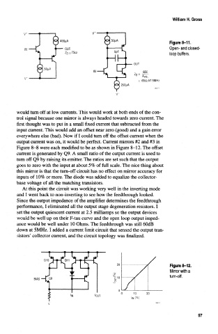
Figure 8-11
OUT Open- and closed-
Z 0 a 750 loop buffers.
AVOL
s 650 AT 5MHz
would turn off at low currents. This would work at both ends of the con-
trol signal because one mirror is always headed towards zero current. The
first thought was to put in a small fixed current that subtracted from the
input current. This would add an offset near zero (good) and a gain error
everywhere else (bad). Now if I could turn off the offset current when the
output current was on, it would be perfect. Current mirrors #2 and #3 in
Figure 8-8 were each modified to be as shown in Figure 8-12. The offset
current is generated by Q9. A small ratio of the output current is used to
turn off Q9 by raising its emitter. The ratios are set such that the output
goes to zero with the input at about 5% of full scale. The nice thing about
this mirror is that the turn-off circuit has no effect on mirror accuracy for
inputs of 10% or more. The diode was added to equalize the collector-
base voltage of all the matching transistors.
At this point the circuit was working very well in the inverting mode
and I went back to non-inverting to see how the feedthrough looked.
Since the output impedance of the amplifier determines the feedthrough
performance, I eliminated all the output stage degeneration resistors. I
set the output quiescent current at 2.5 milliamps so the output devices
would be well up on their F-tau curve and the open loop output imped-
ance would be well under 10 Ohms. The feedthrough was still 60dB
down at 5MHz. I added a current limit circuit that sensed the output tran-
sistors* collector current, and the circuit topology was finalized.
20 Figure 8-12.
Mirror with a
turn-off.
."10
0 10 20
IOUT
IIN (%)
97