
Page 174 - The Art and Science of Analog Circuit Design
P. 174
Tripping the Light Fantastic
1 IU
100
Figure 11-14. __ gfl T
Ambient tempera- ?i LAMP ! = 5mA
/ . _ TYPICAL
ENCLOSURE
/
7
lure effects on | , n — f— — TEMPERATURE"
• • •*. i ^ °
emissivtty of a § — ATT A = 25T
typical 5mA lamp, | -A — i —
Lamp and encio- £ J H-4-
sure must come to | / ^NORMALIZED
thermal steady ^ V T025°C
r 4__
state before \ ]
10 ., ....... J ....... - - f- -
measurements 1
0 I--..— .—L— ..-....-
are made, -30-20-10 o 10 20 30 40 50 so 70 a
CCFL Load Characteristics
These lamps are a difficult load to drive, particularly for a switching regu-
lator. They have a "negative resistance" characteristic; the starting voltage
is significantly higher than the operating voltage. Typically, the start volt-
age is about 1000V, although higher and lower voltage lamps are com-
mon. Operating voltage is usually 300V to 400V, although other lamps
may require different potentials. The lamps will operate from DC» but
migration effects within the lamp will quickly damage it. As such, the
waveform must be AC. No DC content should be present.
Figure 11-17A shows an AC driven lamp's characteristics on a curve
tracer. The negative resistance induced "snapback" is apparent. In Figure
11-17B, another lamp, acting against the curve tracer's drive, produces
oscillation. These tendencies, combined with the frequency compensa-
tion problems associated with switching regulators, can cause severe loop
instabilities, particularly on start-up. Once the lamp is in its operating
region it assumes a linear load characteristic, easing stability criteria.
Lamp operating frequencies are typically 20kHz to 100kHz and a sine-
500
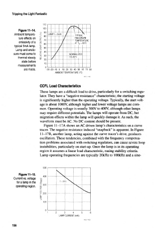
Figure 11-15.
400
Current vs. voltage
for a lamp in the
operating region, 300
> 200 -
100
2 3 4 5
LAMP CURRENT (mA)
156