
Page 176 - The Art and Science of Analog Circuit Design
P. 176
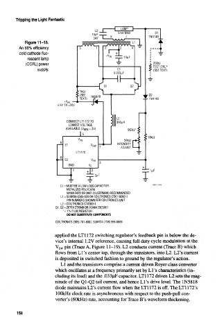
Tripping the Light Fantastic


             Figure 11-18.
          An 88% efficiency
          cold cathode fluo-
              rescent lamp
             (CCFL) power                                            2000
                                                                     TEST ONLY
                  supply.                                            (SEE TEXT)


                           4.5V TO +20V


                               CONNECT LT1172 TO
                                LOWEST VOLTAGE
                               AVAILABLE (M Mm = 3V)
                                     Is
                                    V                   SOkii
                                          "sw        INTENSITY
                                                       ADJUST
                                   LT1172
                              E2           FB
                                GND
                                                                    1MF
                                        HHMIMMI

                            C1 = MUST BE A LOW LOSS CAPACITOR.
                               METALIZED POLYCARB
                               WIMA FKP2 OR MKP-20 (GERMAN) RECOMMENDED
                            L1 = SUMIDA 6345-020 OR COILTRONICS CTX110092-1
                               PIN NUMBERS SHOWN FOR COILTRONICS UNIT
                            L2 = COILTRONICS CTX300-4
                          Q1, 02 = ZETEX ZTX849 OR ROHM 2SC5001
                             *=1% FILM RESISTOR
                               00 NOT SUBSTITUTE COMPONENTS
                          COILTRONICS (305) 781-8900, SUMIDA (708) 956-0666

                          applied the LTl 172 switching regulator's feedback pin is below the de-
                          vice's internal 1.2V reference, causing full duty cycle modulation al the
                          V sw pin (Trace A, Figure 11-19). L2 conducts current (Trace B) which
                          flows from Li's center tap, through the transistors, into L2; L2*s current
                          is deposited in switched fashion to ground by the regulator's action.
                            LI and the transistors comprise a current driven Royer class converter
                          which oscillates at a frequency primarily set by LI's characteristics (in-
                          cluding its load) and the .033uF capacitor. LTl 172 driven L2 sets the mag-
                          nitude of the Q1-Q2 tail current, and hence Li's drive level. The 1N5818
                          diode maintains L2's current flow when the LTl 172 is off. The LTl 172's
                          100kHz clock rate is asynchronous with respect to the push-pull con-
                          verter's (60kHz) rate, accounting for Trace B's waveform thickening.


         158