
Page 175 - The Art and Science of Analog Circuit Design
P. 175
Jim Williams
1000
Figure 11-16.
Running voltage vs.
lamp length at two
temperatures,
Start-up voltages
are usually 50% to
200% higher over
temperature,
100 200
TUBE LENGTH (mm)
like waveform is preferred. The sine drive's low harmonic content mini-
mizes RF emissions, which could cause interference and efficiency
degradation. A further benefit of the continuous sine drive is its low crest
factor and controlled risetimes, which are easily handled by the CCFL.
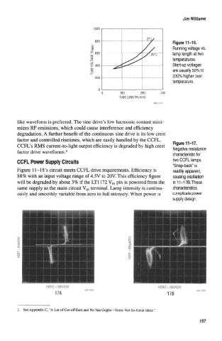
Figwe 11-17.
CCFL's RMS current-to-light output efficiency is degraded by high crest Negative resistance
factor drive waveforms. 2
characteristic for
CCFL Power Supply Circuits two CCFL lamps.
"Snap-back" is
Figure 11-18's circuit meets CCFL drive requirements. Efficiency is readily apparent,
88% with an input voltage range of 4.5V to 20V. This efficiency figure causing oscillation
will be degraded by about 3% if the LT1172 V IN pin is powered from the in 11-17B. These
same supply as the main circuit V IN terminal. Lamp intensity is continu- characteristics
ously and smoothly variable from zero to full intensity. When power is complicate power
supply design.
HORIZ = 200V/DIV HORIZ = 200V/D1V
17A 17B
2, See Appendix C, "A Lot of Cut-off Ears and No Van Goghs—Some Not-So-Great Ideas."
157