
Page 177 - The Art and Science of Analog Circuit Design
P. 177
Jim Williams
jfcjNofetnde-
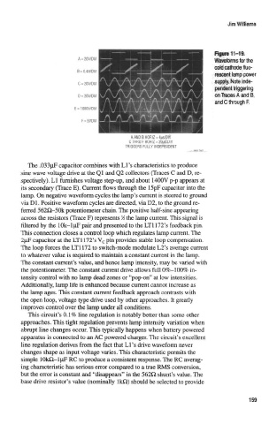
M$tHggprin<
ices A and!
and C through F.
C THRU F HORiZ = 20j|S/DIV
TRIGGERS FULLY INDEPENDENT
The .033^iF capacitor combines with Li's characteristics to produce
sine wave voltage drive at the Ql and Q2 collectors (Traces C and D, re-
spectively). LI famishes voltage step-up, and about 1400V p-p appears at
Its secondary (Trace E). Current flows through the 15pF capacitor into the
lamp. On negative waveform cycles the lamp's current is steered to ground
via Dl. Positive waveform cycles are directed, via D2, to the ground re-
ferred 562Q-50k potentiometer chain. The positive half-sine appearing
1
across the resistors (Trace F) represents A the lamp current. This signal is
filtered by the 10k~ljaF pair and presented to the LT1172's feedback pin.
This connection closes a control loop which regulates lamp current. The
2pF capacitor at the LT1172's V c pin provides stable loop compensation.
The loop forces the LT1172 to switch-mode modulate L2's average current
to whatever value is required to maintain a constant current in the lamp.
"The constant current's value, and hence lamp intensity, may be varied with
the potentiometer. The constant current drive allows full 0%~100% in-
tensity control with no lamp dead zones or "pop-on" at low intensities.
Additionally, lamp life is enhanced because current cannot increase as
the lamp ages. This constant current feedback approach contrasts with
the open loop, voltage type drive used by other approaches. It greatly
improves control over the lamp under all conditions.
This circuit's 0.1% line regulation is notably better than some other
approaches. This tight regulation prevents lamp intensity variation when
abrupt line changes occur. This typically happens when battery powered
apparatus is connected to an AC powered charger. The circuit's excellent
line regulation derives from the fact that Li's drive waveform never
changes shape as input voltage varies. This characteristic permits the
simple 10kO-ljLiF RC to produce a consistent response. The RC averag-
ing characteristic has serious error compared to a true RMS conversion,
but the error is constant and "disappears" in the 562O shunt's value. The
base drive resistor's value (nominally IkO) should be selected to provide
159