
Page 179 - The Art and Science of Analog Circuit Design
P. 179
Jim Williams
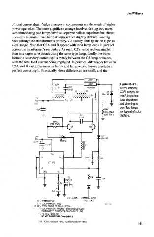
of total current drain. Value changes in components are the result of higher
power operation. The most significant change involves driving two tubes.
Accommodating two lamps involves separate ballast capacitors but circuit
operation is similar. Two lamp designs reflect slightly different loading
back through the transformer's primary. C2 usually ends up in the lOpF to
47pF range. Note that C2A and B appear with their lamp loads in parallel
across the transformer's secondary. As such, C2's value is often smaller
than in a single tube circuit using the same type lamp. Ideally the trans-
former's secondary current splits evenly between the C2-lamp branches,
with the total load current being regulated. In practice, differences between
C2A and B and differences in lamps and lamp wiring layout preclude a
perfect current split. Practically, these differences are small, and the
Figure 11-21.
A 92% efficient
CCFL supply for
10mA loads fea-
tures shutdown
and dimming in-
puts. Two lamps
2QO£i
TEST ONLY are typical of color
s
(SEE TEXT) displays.
2nF
SHUTDOWN DIMMING INPUT
C1 = WIMA MKP-20 ( SEE TEXT )
L1=COILTRONICSCTX150-4
Q1, Q2 = ZETEX ZTX849 OR ROHM 2SC5001
T1 = COILTRONICS CTX110600-1 OR SUMIDA EPS-207
PIN NUMBERS SHOWN FOR COILTRONICS UNIT
* = 1% FILM RESISTOR
DO NOT SUBSTITUTE COMPONENTS
COILTRONICS (305) 781-8900, SUMIDA (708) 956-0666
161