
Page 183 - The Art and Science of Analog Circuit Design
P. 183
Jim Williams
A A A / '1 x I
/ L / -L / -L ON/
N
>\ - xS " xS " / *,*' ' 0
SPLAY HOUSING AN
/ HV / / HV / / ^^-^^ R EFLECTIVE FOIL ON I
/ LEAD WIRE ' I I ' LEAD WIRe r ...... .-— =
/ -^! » ^ 1 1 *— -*: — ^ 1 CCFL LAMP |'iim,ij7 .
L ^ x 1 I N x -^-i-
f \ y OUTPUT \ . N / \ x "^
r /y CAPACITOR >y >y ./
C ' X TYPICALLY ^S '\ /A 1 DESIRED *
V f 15pF-47pF 1 I ' ^ ^ D1 1 ^ CURRENT I ]
c -L -L i ' I "1 FLOW 1
JL
STRAY TO FEEDBACK •
CAPACITANCE CIRCUITRY
1
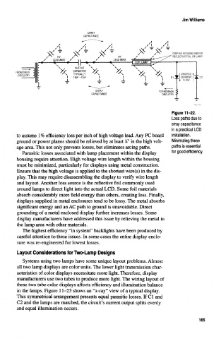
Figure 11-22.
Loss paths due to
stray capacitance
in a practical LCD
to assume 1% efficiency loss per inch of high voltage lead. Any PC board installation.
1
ground or power planes should be relieved by at least A" in the high volt- Minimizing these
age area. This not only prevents losses, but eliminates arcing paths. paths is essential
Parasitic losses associated with lamp placement within the display for good efficiency.
housing require attention. High voltage wire length within the housing
must be minimized, particularly for displays using metal construction.
Ensure that the high voltage is applied to the shortest wire(s) in the dis-
play. This may require disassembling the display to verify wire length
and layout. Another loss source is the reflective foil commonly used
around lamps to direct light into the actual LGD. Some foil materials
absorb considerably more field energy than others, creating loss. Finally,
displays supplied in metal enclosures tend to be lossy. The metal absorbs
significant energy and an AC path to ground is unavoidable. Direct
grounding of a metal enclosed display further increases losses. Some
display manufacturers have addressed this issue by relieving the metal in
the lamp area with other materials.
The highest efficiency "in system" backlights have been produced by
careful attention to these issues. In some cases the entire display enclo-
sure was re-engineered for lowest losses.
Layout Considerations for Two-Lamp Designs
Systems using two lamps have some unique layout problems. Almost
all two lamp displays are color units. The lower light transmission char-
acteristics of color displays necessitate more light. Therefore, display
manufacturers use two tubes to produce more light. The wiring layout of
these two tube color displays affects efficiency and illumination balance
in the lamps. Figure 11-23 shows an "x-ray" view of a typical display.
This symmetrical arrangement presents equal parasitic losses. If Cl and
C2 and the lamps are matched, the circuit's current output splits evenly
and equal illumination occurs.
165