
Page 185 - The Art and Science of Analog Circuit Design
P. 185
Jim Williams
DISPLAY HOUSING
CCFL LAMP h-*
TO TRANSFORMER LCD SCREEN
SECONDARY
C1 <
H
C2
H CCFL LAMP h
C1 > C2 FOR
MISMATCHED
CSTRAY
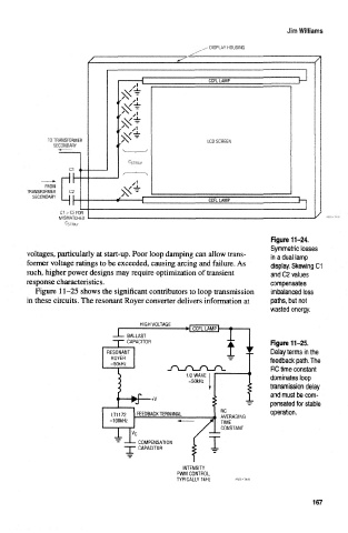
Figure 11-24.
Symmetric tosses
voltages, particularly at start-up. Poor loop damping can allow trans- in a dual lamp
former voltage ratings to be exceeded, causing arcing and failure. As display. Stewing C1
such, higher power designs may require optimization of transient and C2 values
response characteristics. compensates
Figure 11-25 shows the significant contributors to loop transmission imbalaneed loss
in these circuits. The resonant Royer converter delivers information at paths, but not
wasted energy.
i »| CCFL LAMP h— H
—1— BALLAST
— r— CAPACITOR "j Figure 11-25.
\
RESONANT Delay terms in the
ROYER — feedback path. The
=50kHz
-TL^L-nL^X RC time constant
L
dominates loop
=50kHz
transmission delay
and must be com-
•+V
pensated for stable
RC operation.
LT1172 FEEDBACK TERMINAL
, AVERAGING
=100kHz
TIME
/ CONSTANT
/ J
v c
- — COMPENSATION [
-T- CAPACITOR < -!
INTENSITY
PWM CONTROL,
TYPICALLY 1kHz
167