
Page 187 - The Art and Science of Analog Circuit Design
P. 187
Jim Williams
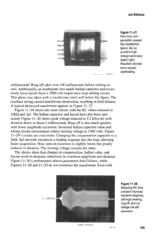
Poor loop com-
pensation caused
this transformer
failure. Arc oc-
curred In high
voltegs secondary
(lower right).
Resultant shorted
turns caused
overheating.
milliseconds! Ring-offtakes over 100 milliseconds before settling oc-
curs. Additionally, an inadequate (too small) ballast capacitor and exces-
sively lossy layout force a 2000 volt output once loop settling occurs.
This photo was taken with a transformer rated well below this figure. The
resultant arcing caused transformer destruction, resulting in field failures.
A typical destroyed transformer appears in Figure 11-27.
Figure 11-28 shows the same circuit, with the RC values reduced to
lOkO and l^if. The ballast capacitor and layout have also been opti-
mized. Figure 11-28 shows peak voltage reduced to 2.2 kilovolts with
duration down to about 2 milliseconds. Ring-off is also much quicker,
with lower amplitude excursion. Increased ballast capacitor value and
wiring layout optimization reduce running voltage to 1300 volts. Figure
11-29's results are even better. Changing the compensation capacitor to a
3kO-2{if network introduces a leading response into the loop, allowing
faster acquisition. Now, turn-on excursion is slightly lower, but greatly
reduced in duration. The running voltage remains the same.
The photos show that changes in compensation, ballast value, and
layout result in dramatic reductions in overshoot amplitude and duration.
Figure 1 l-26's performance almost guarantees field failures, while
Figures 11-28 and 11-29 do not overstress the transformer. Even with
HORIZ = Sms/DIV
169