
Page 188 - The Art and Science of Analog Circuit Design
P. 188
Tripping the Light Fantastic
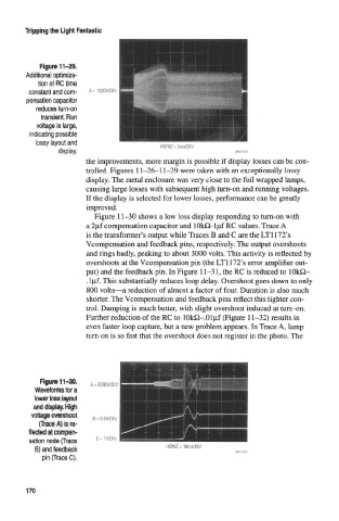
Figure 11-29.
Additional optimiza-
tion of RC time
constant and com-
pensation capacitor
reduces turn-on
transient. Run
voltage is large,
indicating possible
lossy layout and HORIZ = 2ms/DIV
display.
the improvements, more margin is possible if display losses can be con-
trolled. Figures 11-26-11-29 were taken with an exceptionally lossy
display. The metal enclosure was very close to the foil wrapped lamps,
causing large losses with subsequent high turn-on and running voltages.
If the display is selected for lower losses, performance can be greatly
improved.
Figure 11-30 shows a low loss display responding to turn-on with
a 2\if compensation capacitor and 10kH-l|nf RC values. Trace A
is the transformer's output while Traces B and C are the LT1172's
Vcompensation and feedback pins, respectively. The output overshoots
and rings badly, peaking to about 3000 volts. This activity is reflected by
overshoots at the Vcompensation pin (the LT1172's error amplifier out-
put) and the feedback pin. In Figure 11-31, the RC is reduced to lOkQ-
.l[if. This substantially reduces loop delay. Overshoot goes down to only
800 volts—a reduction of almost a factor of four. Duration is also much
shorter. The Vcompensation and feedback pins reflect this tighter con-
trol. Damping is much better, with slight overshoot induced at turn-on.
Further reduction of the RC to lOkQ-.Oljif (Figure 11-32) results in
even faster loop capture, but a new problem appears. In Trace A, lamp
turn on is so fast that the overshoot does not register in the photo. The
Figure 11-30.
WavefofMsfora
fleeted at compen-
sation node (Trace c = IV/DIV
B) and feedback HORIZ = 10ms/DIV
pin (Trace C).
170