
Page 184 - The Art and Science of Analog Circuit Design
P. 184
Tripping the Light Fantastic
DISPLAY HOUSING
CCFL LAMP ]_J
TO TRANSFORMER
SECONDARY
C1 <
LCD SCREEN
FROM
TRANSFORMER
SECONDARY
C1 = C2
FOR MATCHED
CSTRAY
CCFL LAMP h-t
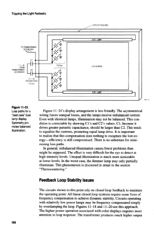
Figure 11-23.
Loss paths for a Figure 11-24's display arrangement is less friendly. The asymmetrical
"best case" dual wiring forces unequal losses, and the lamps receive unbalanced current.
lamp display. Even with identical lamps, illumination may not be balanced. This con-
Symmetry pro- dition is correctable by skewing Cl's and C2's values. Cl, because it
motes balanced drives greater parasitic capacitance, should be larger than C2. This tends
illumination.
to equalize the currents, promoting equal lamp drive. It is important
to realize that this compensation does nothing to recapture the lost en-
ergy—efficiency is still compromised. There is no substitute for mini-
mizing loss paths.
In general, imbalanced illumination causes fewer problems than
might be supposed. The effect is very difficult for the eye to detect at
high intensity levels. Unequal illumination is much more noticeable
at lower levels. In the worst case, the dimmer lamp may only partially
illuminate. This phenomenon is discussed in detail in the section
' Thermometering.''
Feedback Loop Stability Issues
The circuits shown to this point rely on closed loop feedback to maintain
the operating point. All linear closed loop systems require some form of
frequency compensation to achieve dynamic stability. Circuits operating
with relatively low power lamps may be frequency compensated simply
by overdamping the loop. Figures 11-18 and 11-20 use this approach.
The higher power operation associated with color displays requires more
attention to loop response. The transformer produces much higher output
166