
Page 189 - The Art and Science of Analog Circuit Design
P. 189
Jim Williams
1:1-31,
A = 2000WDIV
B = 0.5WPlf
C = 1V/DIV running voltage.
HORIZ = 10rns/DIV
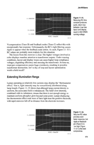
Vcompensation (Trace B) and feedback nodes (Trace C) reflect this with
exceptionally fast response. Unfortunately, the RC's light filtering causes
ripple to appear when the feedback node settles. As such, Figure 11-31 's
RC values are probably more realistic for this situation.
The lesson from this exercise is clear. The higher voltages involved in
color displays mandate attention to transformer outputs. Under running
conditions, layout and display losses can cause higher loop compliance
voltages, degrading efficiency and stressing the transformer. At turn-on,
improper compensation causes huge overshoots, resulting in possible
transformer destruction. Isn't a day of loop and layout optimization
worth a field recall?
Extending Illumination Range
Lamps operating at relatively low currents may display the "thermometer
effect," that is, light intensity may be nonuniformly distributed along
lamp length. Figure 11-33 shows that although lamp current density is
uniform, the associated field is imbalanced. The field's low intensity,
combined with its imbalance, means that there is not enough energy to
maintain uniform phosphor glow beyond some point. Lamps displaying
the thermometer effect emit most of their light near the positive electrode,
with rapid emission fall-off as distance from the electrode increases.
isBe lest
C = 1WDIV
compromise.
HORIZ = 10ms/DIV
171