
Page 186 - The Art and Science of Analog Circuit Design
P. 186
Tripping the Light Fantastic
about 50kHz to the lamp. This information is smoothed by the RC aver-
aging time constant and delivered to the LT1172's feedback terminal as
DC, The LT1172 controls the Royer converter at a 100kHz rate, closing
the control loop. The capacitor at the LT1172 rolls off gain, nominally
stabilizing the loop. This compensation capacitor must roil off the gain
bandwidth at a low enough value to prevent the various loop delays from
causing oscillation.
Which of these delays is the most significant? From a stability view-
point, the LT1172's output repetition rate and the Royer's oscillation
frequency are sampled data systems. Their information delivery rate is
far above the RC averaging time constant's delay and is not significant.
The RC time constant is the major contributor to loop delay. This time
constant must be large enough to turn the half wave rectified waveform
into DC. It also must be large enough to average any intensity control
PWM signal to DC. Typically, these PWM intensity control signals come
in at a 1kHz rate. The RC's resultant delay dominates loop transmission.
It must be compensated by the capacitor at the LT1172. A large enough
value for this capacitor rolls off loop gain at low enough frequency to
provide stability. The loop simply does not have enough gain to oscillate
at a frequency commensurate with the RC delay.
This form of compensation is simple and effective. It ensures stability
over a wide range of operating conditions. It does, however, have poorly
damped response at system turn-on. At turn-on, the RC lag delays feed-
back, allowing output excursions well above the normal operating point.
When the RC acquires the feedback value, the loop stabilizes properly.
This turn-on overshoot is not a concern if it is well within transformer
breakdown ratings. Color displays, running at higher power, usually re-
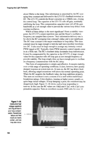
quire large initial voltages. If loop damping is poor, the overshoot may be
dangerously high. Figure 11-26 shows such a loop responding to
turn-on. In this case the RC values are 1 OkO and 4.7jif, with a 2pf com-
pensation capacitor. Turn-on overshoot exceeds 3500 volts for over 10
Figure 11-26.
Destactivi high
voltage overshoot
and ring-off due to
poor loop compen-
sation. Transformer
= 1000V/DtV
failure and field
recall are nearly
certain. Job loss
may also occur.
HORIZ = 20ms/D!V
168