
Page 84 - The Art and Science of Analog Circuit Design
P. 84
Steve Roach
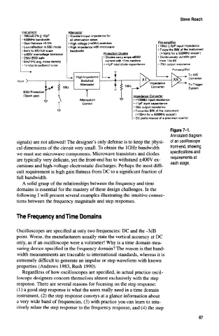
Instrument Attenuator
• 1MQ*0.2% || 10pF • Constant input impedance for
• 500MHz ijandwidth all attenuation steps
• Gain flatness <0.5% • High voltage (>400V) switches Pre-amplifier
• Low reflection in 500 mode • High impedance with microwave • 10ki2 H 2pF input impedance
• 8mV to 40V full scale bandwidth • Twice the BW of the instrument
• ±400V overvoltage tolerance Protection Diodes (>1GHz for a 500MHz scope!)
» 25W ESD safe • Diodes carry amps ofESD • Continuously variable gain
• SnV/VHz avg. noise density current with <1ns risetfme from 1 to 50
• 1 mVpp broadband noise • <1pF total diode capacitance • 7QQ output resistance
Pre-amptifier
— »
. ToA/D
1 — » High Impedance
input y »*-—— "•-"• •"•"" 1 Switched 1 i — Converter
L i Attenuator •j ^* 1MW Impedance To Trigger
Converter
'*Jt < 50< I
' 1 ^ ? System
3 Protection
>ark gap) ! Impedance Converter
Imfie
Attenuation • >10 100MQ input resistance
Control <1pF input capacitance
50Q output resistance
Twice the BW of the instrument
(>1 GHz for a 500MHz scope!)
DC performance of a precision opamp
Figure 7-1.
Annotated diagram
signals) are not allowed! The designer's only defense is to keep the physi- of an oscilloscope
cal dimensions of the circuit very small To obtain the 1 GHz bandwidth front-end, showing
we must use microwave components. Microwave transistors and diodes specifications and
are typically very delicate, yet the front-end has to withstand ±400V ex- requirements at
each stage.
cursions and high-voltage electrostatic discharges. Perhaps the most diffi-
cult requirement is high gain flatness from DC to a significant fraction of
full bandwidth.
A solid grasp of the relationships between the frequency and time
domains is essential for the mastery of these design challenges. In the
following I will present several examples illustrating the intuitive connec-
tions between the frequency magnitude and step responses.
The Frequency and Time Domains
Oscilloscopes are specified at only two frequencies: DC and the -3dB
point. Worse, the manufacturers usually state the vertical accuracy at DC
only, as if an oscilloscope were a voltmeter! Why is a time domain mea-
suring device specified in the frequency domain? The reason is that band-
width measurements are traceable to international standards, whereas it is
extremely difficult to generate an impulse or step waveform with known
properties (Andrews 1983, Rush 1990).
Regardless of how oscilloscopes are specified, in actual practice oscil-
loscope designers concern themselves almost exclusively with the step
response. There are several reasons for focusing on the step response:
(1) a good step response is what the users really need in a time domain
instrument, (2) the step response conveys at a glance information about
a very wide band of frequencies, (3) with practice you can learn to intu-
itively relate the step response to the frequency response, and (4) the step
67