
Page 86 - The Art and Science of Analog Circuit Design
P. 86
Steve Roach
(Kamath 1974). Thus the step response contains information about a very
wide band of frequencies, when observed over a long enough time pe-
riod. For example, looking at the first ten nanoseconds (ns) of the step
conveys frequency domain information from the upper bandwidth of the
instrument down to approximately l/(10ns) or 100MHz.
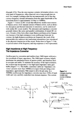
Figure 7-3 shows an RC circuit that effectively models most sources
of flatness errors. Even unusual sources of flatness errors, such as dielec-
tric absorption and thermal transients in transistors, can be understood
with similar RC circuit models. The attenuator and impedance converter
generally behave like series and parallel combinations of simple RC cir-
cuits. Circuits of this form often create flatness problems at low frequen-
cies because of the high resistances in an oscilloscope front-end. In
contrast, the high-frequency problems are frequently the result of the
innumerable tiny inductors and inadvertent transmission lines introduced
in the physical construction of the circuit. Notice how in Figure 7-3 the
reciprocal nature of the frequency and step responses is well represented.
High Impedance at High Frequency:
The Impedance Converter
Oscilloscopes by convention and tradition have 1MQ inputs with just a
few picofarads of input capacitance. The 1MO input resistance largely
determines the attenuation factor of passive probes, and therefore must
be accurate and stable. To maintain the accuracy of the input resistance,
the oscilloscope incorporates a very high input impedance unity gain
buffer (Figure 7-1). This buffer, sometimes called an "impedance con-
verter," presents more than 100MH at its input while providing a low-
impedance, approximately 50Q output to drive the pre-amp. In a Figure 7-3.
500MHz oscilloscope the impedance converter may have IGHz of band- A simple circuit that
width and very carefully controlled time domain response. This section models most
sources of flatness
errors.
lv ft(t)/v,(f)l ' C 1 too big
v>/
i
R 1C 1 =R 2C 2
Magnitude Response
Step Response
69