
Page 274 - The Geological Interpretation of Well Logs
P. 274
- THE GEOLOGICAL INTERPRETATION OF WELL LOGS -
This directly measured textural information is essential when imaged at the borehole wall surface, are difficult to
to the petrophysicist, bul so are the geological associa- differentiate from fully penetrating natural fractures
tions. The too] idendfies pore size distributions which (Chapter 13). Imaging tools do now exist, however, in
can be interpreted in terms of porosity and permeability: which the measured signals are received from deeper in
it is geological analysis that recognises grainstones as the formation. The ARI {azimuthal resistivity imager) of
opposed to vuggy limestones, facies effects as opposed Schlumberger is such a tool, having 12 electrodes spaced
to diagenetic effects. The data set becomes common around the circumference of the sonde and with a depth
ground for both the petrophysicist and the geologist, to of investigation similar to that of the deep laterolog. The
the mutual benefit of both. ‘Best guess’ petrophysical 12. resistivily measurements can be processed into an
formulae will not be required once direct measurements, image in the same way as for other imaging logs,
such as these from the NMR, become available. The although the pixels are much coarser. The signal how-
directly measured characteristics will, importantly, ever, is from beyond dniling damage. potentially, for
require a geological context. example, beyond drilling induced fractures.
The implications of this tool for imaging logs in
general are indeed interesting. Recent logging develop-
16.4 An image of the future
ments have seen two branches: the imaging branch, in
Image fogging technology is in its infancy. But even so which muitiple sensors give a flat, but oriented set of
the information thal the logs contain is amazing. The readings from around the borehole and the other branch,
first reaction of oil industry users has stopped at the also imaged, in which multiple sensors have different
amazement. But the service company developers are depths of investigation but are not oriented. Combining
pushing ahead with both new tools and new software. these two branches will give us full borehole coverage
They seem to have a clear idea of what they want; much with multiple depths of investigation. We shall then be
more so than users. First some comments on the tools able to investigate a ‘virtual’ volume around the borehole.
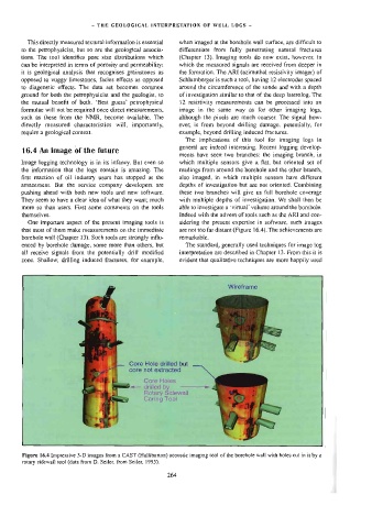
themselves. Indeed with the advent of tools such as the ARI and con-
One important aspect of the present imaging tools is sidering the present expertise in software, such images
that most of them make measurements on the immediate are not too far distant (Figure 16.4). The achievements are
borehole wal! (Chapter 13), Such tools are strongly influ- remarkable.
enced by borehole damage, some more than others, but The standard, generally used techniques for image log
al] receive signals from the potentially drill modified interpretation are described in Chapter 13. From this it is
zone. Shallow, drilling induced fractures, for example, evident that qualitative techniques are more happily used
Wireframe
Core Hole drilled but
core not extracted
Core Holes
drilled b —<——————
Rotary idewall
Caring Tool
Figare 16.4 Impressive 3-D images from a CAST (Halliburton) acousuc imaging tool of the borehole wall with holes cut in it by a
rotary sidewall} tool (data from D. Seiler, from Seiler, 1995).
264