
Page 218 - The Jet Engine
P. 218
Thrust distribution
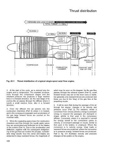
Fig. 20-1 Thrust distribution of a typical single-spool axial flow engine.
3. At the start of the cycle, air is induced into the which may be seen on the diagram. As the gas flow
engine and is compressed. The rearward accelera- passes through the exhaust system (Part 6), small
tions through the compressor stages and the forward forces may act on the inner cone or bullet,
resultant pressure rise produces a large reactive but generally only rearward forces are produced and
force in a forward direction. On the next stage of its these are due to the 'drag' of the gas flow at the
journey the air passes through the diffuser where it propelling nozzle.
exerts a small reactive force, also in a forward
direction, 6. It will be seen that during the passage of the air
through the engine, changes in its velocity and
4. From the diffuser the air passes into the pressure occur (Part 2). For instance, where a
combustion chambers (Part 4) where it is heated, conversion from velocity (kinetic) energy to pressure
and in the consequent expansion and acceleration of energy is required the passages are divergent in
the gas large forward forces are exerted on the shape, similar to that used in the compressor
chamber walls.
diffuser. Conversely, where it is required to convert
5. When the expanding gases leave the combustion the energy stored in the combustion gases to
chambers and flow through the nozzle guide vanes velocity, a convergent passage or nozzle, similar to
they are accelerated and deflected on to the blades that used in the turbine, is employed. Where the
of the turbine (Part 5). Due to the acceleration and conversion is to velocity energy, 'drag' loads or
deflection, together with the subsequent straighten- rearward forces are produced; where the conversion
ing of the gas flow as it enters the jet pipe, consider- is to pressure energy, forward forces are produced.
able 'drag' results; thus the vanes and blades are Part 2, fig. 2-3 illustrates velocity and pressure
subjected to large rearward forces, the magnitude of changes at two points on the engine.
208