
Page 219 - The Jet Engine
P. 219
Thrust distribution
METHOD OF CALCULATING THE THRUST the compressor and the conditions at the outlet from
FORCES the compressor. Since the pressure and the velocity
at the inlet to the compressor are zero, it is only
7. The thrust forces or gas loads can be calculated necessary to consider the force at the outlet from the
for the engine, or for any flow section of the engine, compressor. Therefore, given that the compressor-
provided that the areas, pressures, velocities and
mass flow are known for both the inlet and outlet of OUTLET Area (A) = 182 sq.in.
the particular flow section. Pressure (P) = 94 lb. per sq.in.
(gauge)
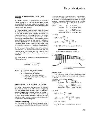
8. The distribution of thrust forces shown in fig. 20- Velocity ) = 406 ft. per sec.
(v J
1 can be calculated by considering each component Mass flow (W) = 153 lb. per sec.
in turn and applying some simple calculations. The
thrust produced by the engine is mainly the product The thrust
of the mass of air passing through the engine and the MV J
velocity increase imparted to it (i.e. Newtons Second = ( A x P ) + g − 0
Law of Motion), however, the pressure difference
between the inlet to and the outlet from the particular = ( 182 x 94 ) + 153 x 406 − 0
flow section will have an effect on the overall thrust 32
of the engine and must be included in the calculation.
= 19,049 lb. of thrust in a forward direction.
9. To calculate the resultant thrust for a particular
flow section it is necessary to calculate the total
thrust at both inlet and outlet, the resultant thrust
being the difference between the two values
obtained.
10. Calculation of the thrust is achieved using the
following formula:
Thrust = ( A x P ) + M JV
g
Where A = Area of flow section in sq.in.
P = Pressure in lb. per sq.in. Diffuser duct
W = Mass flow in lb. per sec. 13. The conditions at the diffuser duct inlet are the
= Velocity of flow in feet per sec.
v J same as the conditions at the compressor outlet, i.e.
g = Gravitational constant 32.2 ft. per 19,049 lb.
sec. per sec.
Therefore, given that the diffuser--
OUTLET Area (A) = 205 sq.in.
Pressure (P) = 95 lb. per sq.in.
CALCULATING THE THRUST OF THE ENGINE (gauge)
Velocity (v J ) = 368 ft. per sec.
11. When applying the above method to calculate Mass flow (W) = 153 lb. per sec.
the individual thrust loads on the various components
it is assumed that the engine is static. The effect of The thrust
aircraft forward speed on the engine thrust will be WV J
dealt with in Part 21. In the following calculations 'g' = ( A x P ) + g − 19 , 049
is taken to be 32 for convenience. To assist in these
calculations the locations concerned are illustrated 153 x 368
by a number of small diagrams. = ( 205 x 95 ) + 32 − 19 , 049
Compressor casing = 21,235 - 19,049
12. To obtain the thrust on the compressor casing it
is necessary to calculate the conditions at the inlet to = 2,186 lb. of thrust in a forward direction.
209