
Page 222 - The Jet Engine
P. 222
Thrust distribution
across the exit area of the propelling nozzle by combining the gas loads on the individual
(pressure thrust). Algebraically, this force is engine locations.
) A.
expressed as (P-P 0
21. On engines that operate with a non-choked
Where A = Area of propelling nozzle in sq.in. nozzle, the (P-P 0 ) A function does not apply and the
P = Pressure in lb. per sq.in. thrust results only from the gas stream momentum
= Atmospheric pressure in lb. per sq.in.
P 0 change.
Therefore, assuming values of mass flow, pressure Inclined combustion chambers
and area to be the same as in the previous calcula- 22. In the previous example (Para. 14) the flow
tions i.e. through the combustion chamber is axial, however, if
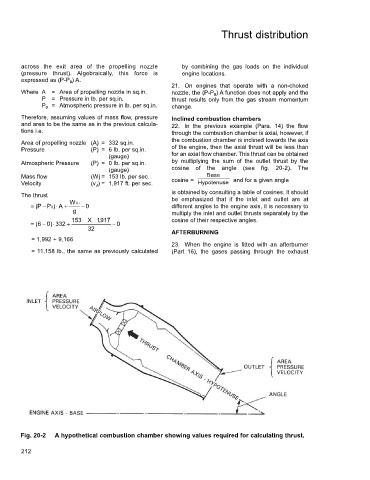
the combustion chamber is inclined towards the axis
Area of propelling nozzle (A) = 332 sq.in.
Pressure (P) = 6 lb. per sq.in. of the engine, then the axial thrust will be less than
(gauge) for an axial flow chamber. This thrust can be obtained
Atmospheric Pressure (P) = 0 lb. per sq.in. by multiplying the sum of the outlet thrust by the
(gauge) cosine of the angle (see fig. 20-2). The
Mass flow (W) = 153 lb. per sec. Base
Hypotenuse
Velocity (v J ) = 1,917 ft. per sec. cosine = and for a given angle
is obtained by consulting a table of cosines. It should
The thrust
be emphasized that if the inlet and outlet are at
= P ( − P0 )⋅ A + WV J − 0 different angles to the engine axis, it is necessary to
g multiply the inlet and outlet thrusts separately by the
153 X , 1 917 cosine of their respective angles.
= 6 ( − ) 0 ⋅ 332 + − 0
32
AFTERBURNING
= 1,992 + 9,166
23. When the engine is fitted with an afterburner
= 11,158 lb., the same as previously calculated (Part 16), the gases passing through the exhaust
Fig. 20-2 A hypothetical combustion chamber showing values required for calculating thrust.
212