
Page 217 - The Jet Engine
P. 217
20: Thrust distribution
Contents Page
Introduction 207
Distribution of the thrust
forces 207
Method of calculating the
thrust forces 209
Calculating the thrust of
the engine 209
Compressor casing
Diffuser duct
Combustion chambers
Turbine assembly
Exhaust unit and jet pipe
Propelling nozzle
Engine
Inclined combustion chambers
Afterburning 212
INTRODUCTION the sum of the forward forces exceeds the sum of the
rearward forces is normally known as the rated thrust
1. Although the principles of jet propulsion (see Part of the engine.
1) will be familiar to the reader, the distribution of the
thrust forces within the engine may appear DISTRIBUTION OF THE THRUST FORCES
somewhat obscure- These forces are in effect gas
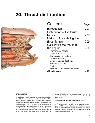
loads resulting from the pressure and momentum 2. The diagram in fig. 20-1 is of a typical single-
changes of the gas stream reacting on the engine spool axial flow turbo-jet engine and illustrates where
structure and on the rotating components. They are the main forward and rearward forces act. The origin
in some locations forward propelling forces and in of these forces is explained by following the engine
others opposing or rearward forces. The amount that working cycle shown in Part 2.
207