
Page 131 -
P. 131
The Practical Pumping Handbook ~- _ ........ ------:_ ..... iiiii .... iiiiiiiii__ ..... iiiiiiiiiiiii_
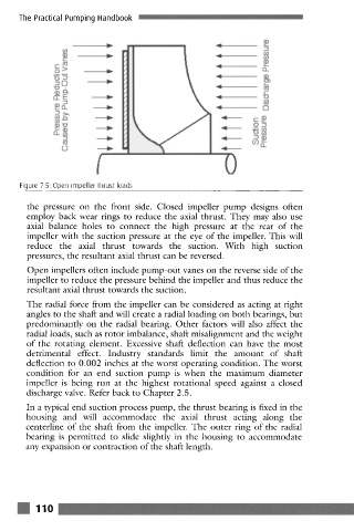
Figure 7.5: Open impeller thrust loads
the pressure on the front side. Closed impeller pump designs often
employ back wear rings to reduce the axial thrust. They may also use
axial balance holes to connect the high pressure at the rear of the
impeller with the suction pressure at the eye of the impeller. This will
reduce the axial thrust towards the suction. With high suction
pressures, the resultant axial thrust can be reversed.
Open impellers often include pump-out vanes on the reverse side of the
impeller to reduce the pressure behind the impeller and thus reduce the
resultant axial thrust towards the suction.
The radial force from the impeller can be considered as acting at right
angles to the shaft and will create a radial loading on both bearings, but
predominantly on the radial bearing. Other factors will also affect the
radial loads, such as rotor imbalance, shaft misalignment and the weight
of the rotating element. Excessive shaft deflection can have the most
detrimental effect. Industry standards limit the amount of shaft
deflection to 0.002 inches at the worst operating condition. The worst
condition for an end suction pump is when the maximum diameter
impeller is being run at the highest rotational speed against a closed
discharge valve. Refer back to Chapter 2.5.
In a typical end suction process pump, the thrust bearing is fixed in the
housing and will accommodate the axial thrust acting along the
centerline of the shaft from the impeller. The outer ring of the radial
bearing is permitted to slide slightly in the housing to accommodate
any expansion or contraction of the shaft length.
ill 110
~ .