
Page 137 -
P. 137
The Practical Pumping Handbook LIIIIIIIIIIIIIIIIIII ....... iiiiiiiiiiiiiiiiii ............... iiiiiiiii11117711 ............ ~iiiii ::iiii::+~+ ~ +
When a sight glass is used in the '-I I'
bearing housing, it tends to
provide a more dependable
indication of oil level and quality
than the constant level oiler.
However, it is worthwhile to be
aware that the oil level shown in
the sight glass may vary slightly
when the pump is operating,
depending on the direction of i+++i+i+!++i++++++++++++
shaft rotation and the type of sight l iii i ii +ii iii ii iiiil
glass used. Figure 7.13: Diagram of oiler and level in
bearings
7.6.2 Constant level oiler
As it's name implies, the constant level oiler is used to maintain a
constant level of the oil in the oil sump or bearing housing. As the oil
level is lowered, air enters the oiler and forces the lubricating oil in the
oiler to enter the housing. In this way, a constant level of oil is
maintained in the bearing housing. It should be noted that, without
ongoing maintenance, the constant level oiler has a tendency to clog
and thus display a false impression of oil level and quality.
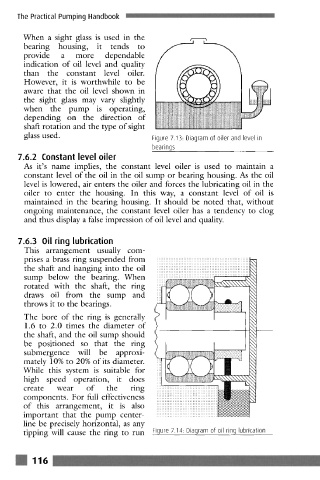
7.6.3 Oil ring lubrication
This arrangement usually com-
prises a brass ring suspended from ::::::::::::::::::::::::::::::::::::::::::::::::::::::::
::::::::::::::::::::::::::::::::::::::::::::::::::::::::
the shaft and hanging into the oil ::::::::::::::::::::::::::::::::::::::::::::::::::::::::
::::::::::::::::::::::::::::::::::::::::::::::::::::::::
::::::::::::::::::::::::::::::::::::::::::::::::::::::::
sump below the bearing. When :::::::::::::::::::::::::::::::::: ......................
rotated with the shaft, the ring
draws oil from the sump and
throws it to the bearings.
The bore of the ring is generally
1.6 to 2.0 times the diameter of
the shaft, and the oil sump should
be positioned so that the ring
submergence will be approxi-
mately 10% to 20% of its diameter.
While this system is suitable for
high speed operation, it does
create wear of the ring
:::::::::::::::::::::::::::::::::::::
components. For full effectiveness .....................................
:::::::::::::::::::::::::::::::::::::
:::::::::::::::::::::::::::::::::::::
of this arrangement, it is also ::::::::::::::::::::::::::::::::::::
....................................
....................................
important that the pump center- ::::::::::::::::::::::::::::::::::::
::::::::::::::::::::::::::::::::::::
line be precisely horizontal, as any
tipping will cause the ring to run Figure 7.14: Diagram of oil ring lubrication
m 116 ._~ ................ ...+_ ,, -++ . . . . . l ................................ I ......................... it .............................. : ....... o,+