
Page 152 - The Toyota Way Fieldbook
P. 152
Chapter 6. Establish Standardized Processes and Procedures 129
likely be the waste of waiting by the operator. The operator may perform mis-
cellaneous tasks to “keep busy,” such as getting the next parts ready or “organ-
izing” the work area (we observed one operator neatly restacking every part in
the bin, which looked nice but was of no value). It is not clear what the cycle
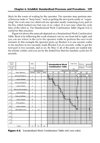
time of the robot is. The Standardized Work Combination Table (Figure 6-6) is
useful for this situation.
Figure 6-6 shows the same job depicted on a Standardized Work Combination
Table. Read it by following the work elements one by one from left to right, and
you can see where in the cycle the operator walks to perform the next work
element. In this example the operator picks up Bracket A in one second, walks
to the machine in two seconds, loads Bracket A in six seconds, walks to get the
next part in two seconds, and so on. By Step 11 all of the parts are loaded into
the robotic welder, and you see by the dotted line that the machine cycles for 23
seconds.
Process
Name Date: Standardized Work Takt Time Manual
Automatic
Part Name Combination Table Walking
Part# Group: 76
Time Elements Operation Time (Seconds)
# Work Elements Manual Auto Walk 10 20 30 40 50 60 70
1 Pick up Bracket A 1 2 Wait Time
2 Load in fixture 6 2
3 Pick up Bracket B 1 3
4 Load in fixture 5 3
5 Pick up Side Support 1 1
6 Load in fixture 3 1
7 Pick up Stiffener 1 2
8 Load in fixture 8 2
9 Pick up Brace 1 3
10 Load in fixture 5 3
11 Start Robot cycle 1 23 1
12
13
14
15
Totals 33 21 23
Figure 6-6. Standardized Work Combination Table with one robot