
Page 172 - The Tribology Handbook
P. 172
B3 Gears
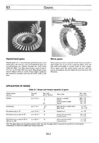
Hypoid bevel gears Worm gears
Hypoid gears are a cross between spiral bevel gears and Worm gears are used to transmit motion between shafts at
worm gears, the axes of a pair of hypoid bevel gears are right angles that do not lie in a common plane. They are
non-intersecting, the distance between the 'axes' being also used occasionally to connect shafts at other angles.
called the offset. The offset allows higher ratios of reduc- Worm gears have line tooth contact and are used for
tion than practicable with bevel gears. Hypoid gears have power transmission, but the higher the ratio the lower the
curved oblique teeth on which contact begins gradually efficiency.
and continues smoothly from one end of the tooth to the
other.
APPLICATION OF GEARS
Table 3.1 Scope and torque capacity of gears
Relation between Max. tooth Max. wheel
shaft axes speed V (M/Sec) Type of tooth torque (Nm)
Parallel up to 10 to 1 5 Helical or straight goo x io4
25 Helical 220 x io4
Profile ground straight 22 x io4
205 Helical 56 x io4
Intersecting up to 7 to 1 2.5 Spiral bevel or straight bevel 9 x io4
60 Spiral bevel 4.5 x io4
Non-intersecting at 90" up to 10 to 1 60 Hypoid bevel 6 X lo4
Non-intersecting crossed at 90" up to 50 to 1 50 Worm and wormwheel 28 x io4
Crossed helical 17 x io4
Non-intersecting crossed at 80" to up to 50 to 1 50 Worm and wormwheel 11 x io4
100" but not 90" Crossed helical 17 x io4
~~
Note: The above figures are for general guidance only. Any case that approaches or exceeds the quoted limits needs special
consideration of details of available gear-cutting equipment.
B3.2