
Page 239 - The Tribology Handbook
P. 239
B16 Pistons
Piston dimensions
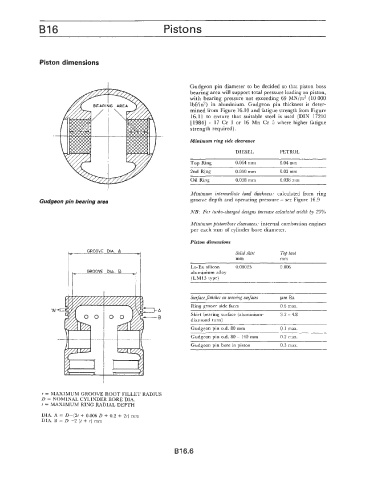
Gudgeon pin diameter to be decided so that piston boss
bearing area will support total pressure loading on piston,
with bearing pressure not exceeding 69 MN/m2 (10 000
Ibf/in2) in aluminium. Gudgeon pin thickness is deter-
mined from Figure 16.10 and fatigue strength from Figure
16.11 to ensure that suitable steel is used (DIN 17210
[1984] - 17 Cr 3 or 16 Mn Cr 5 where higher fatigue
strength required).
Minimum ring side clearance
DIESEL PETROL
Top Ring 0.064 mm 0.04 mm
2nd Rins 0.050 mm 0.03 mm
Oil Ring 0.038 mm 0.038 mm
Minimum intermediate land thickness: calculated from ring
Gudgeon pin bearing area groove depth and operating pressure - see Figure 16.9
NB: For turbo-charged designs increase calculated width 29%
Minimum pistodbore clearances: internal combustion engines
per each mm of cylinder bore diameter.
Piston dimensions
Solid skirt Top land
mm mm
Lo-Ex silicon 0.00025 0.006
aluminium alloy
(LM13 type)
Surface finishes on wearing surfaces pm Ra
Ring groove side faces 0.6 max.
Skirt bearing surface (aluminium- 3.2 - 4.8
diamond turn)
Gudgeon pin 0.d. 80 mm 0.1 max.
Gudgeon pin 0.d. 80 - 140 mm 0.2 max.
Gudgeon pin bore in piston 0.3 rnax.
r = MAXIMUM GROOVE ROOT FILLET RADIUS
D = NOMINAL CYLINDER BORE DIA.
t = MAXIMUM RING RADIAL DEPTH
DIA. A = D-(2t + 0.006 D + 0.2 + 2r) mm
DIA. B = D -2 (t + r) mm
B16.6